Re-coding the remote plip
The remote control on a BX uses a TEA5500 chip for both the transmitter and receiver. This device has ten programming inputs and each input has three possible states, connected to the high or low bus or, unusually, left unconnected. This gives 59,047 possible combinations of code.
When manufactured, all program pins are connected to both the high and low buses. To program the unit, the connecting links on the printed circuit boards are broken by drilling them out. It should be a simple matter, therefore, to re-code either the receiver or the transmitter. For reasons best known to Philips it's not as simple as it could be, the order of the pins is reversed and the logic levels have a peculiar quirk in that low on a transmitter becomes unconnected on the receiver and vice-versa.
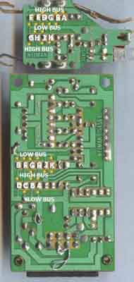 On the picture, this connecting points are marked with letters (if the picture is not legible enough, the rows are as follows: transmitter upper row = FEDCBA, lower row = GHJK; receiver upper row = EFGHJK, lower row = DCBA) and the cut tracks are in yellow.
Step 1: To match a transmitter to a receiver (or vice versa), start with a table like this and fill in the Actual column with the words low, high and open, depending on whether the given connecting point is connected to the low or high bus or left unconnected (in this example, we'll use the setup on the picture):
| Transmitter | Receiver | ||
|---|---|---|---|
| Point | Actual | Point | Required |
| A | low | K | ? |
| B | open | J | ? |
| C | high | H | ? |
| D | open | G | ? |
| E | high | F | ? |
| F | high | E | ? |
| G | low | D | ? |
| H | high | C | ? |
| J | open | B | ? |
| K | low | A | ? |
Step 2: Then, copy the contents of the Actual column, row for row, to the Required column, noting that low should become open and vice versa; high remains unmodified:
| Transmitter | Receiver | ||
|---|---|---|---|
| Point | Actual | Point | Required |
| A | low | K | open |
| B | open | J | low |
| C | high | H | high |
| D | open | G | low |
| E | high | F | high |
| F | high | E | high |
| G | low | D | open |
| H | high | C | high |
| J | open | B | low |
| K | low | A | open |
Finally, use the Required column to determine how you need to set up the receiver: break the existing connection link if it is not needed any more or solder a small wire link if a new connection is required. You can go in the opposite direction as well, if you have the receiver and want to match the remote transmitter to it.
When you refit the trasmitter PCB into the case, be careful not to damage the case protrusion near the area marked with low bus.
Bob SMITH