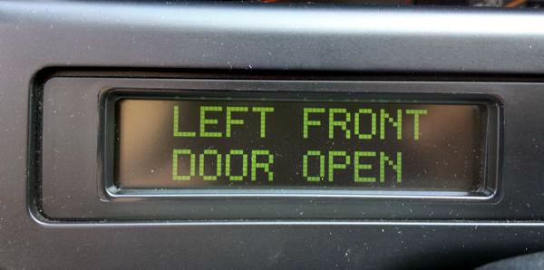
Missing pixel columns on the LHD display
The dot matrix display to the left of the steering wheel of the Series II is known to develop an annoying fault: missing pixel columns. Being rather unsightly to look at, this might sometimes completely ruin our enjoyment of the all too common ABS OUT OF USE readout. :-)
![]()
Fortunately, repairing it is not impossible at all. To access it, you need to remove the complete display housing above and around the steering column. There are five Torx screws located in the lower edge of the housing, two on the left (where this upper panel joins the lower shroud also housing the fuse compartment), three on the right side (below the heater or A/C controls, where this upper panel joins the center console).
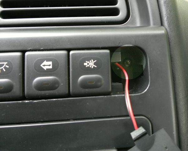
Also, prise free the alarm bulb (or blanking) plate located at the right end of the push button switches in the center. You will see another retaining screw exposed:
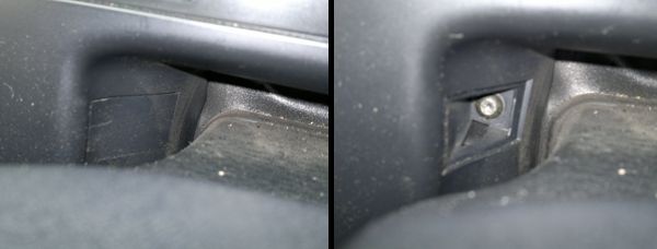
The remaining two screws are located above and behind the steering wheel upper shroud. Lower and pull out the steering wheel as much as possible and you'll see the small covers on each sides. Prise them free with a small screwdriver or your fingernails. Remove the exposed screws. Access is not great, it really helps if you have an universal joint-type extension to your Torx screwdriver.
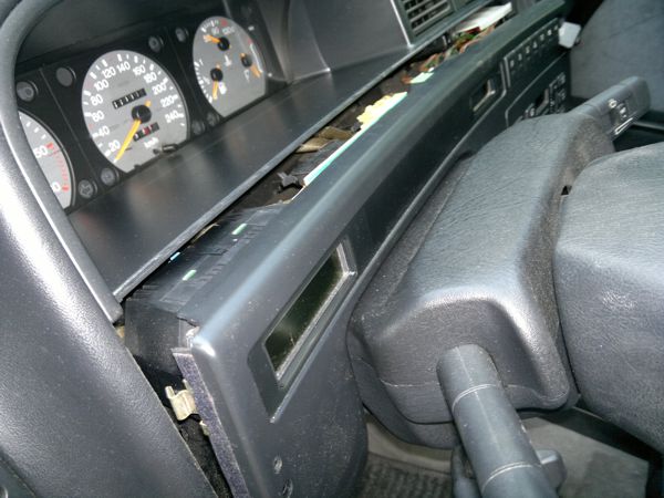
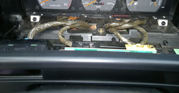
You can now pull out the whole panel (there is a metal lug holding it at the left end, see the picture).
The upper shroud is still in the way and blocking easy access. Although you could remove that, too, I found it easier to make room above. Prise free the cover panel housing the center ventilation controls:

You found a screw here. There are two more in the upper edge of the binnacle around the instrument panel (look out from below) and another one below this first one, now exposed, previously covered by the display surround we have just losened. By removing these four screws, you can pull out the whole instrument binnacle:
Access is much easier now. How you proceed partly depends on your skill now. Actually, especially if it's not the first time you remove the display, you can unclip and remove it from its place now. But if you're still unfamiliar with it, removing the complete shroud might be simpler. Disconnect the display plugs and the switch plugs all around the panel (they are all color coded, no need to mark them or note which goes to which switch and display unit). With every connector disconnected, you can manipulate the shroud from behind the steering wheel (not very easy but certainly possible). If you're not completely confident, use small rags placed beneath the lower corners of the shroud to avoid scratching the other trim panels while manhandling it.
As soon as you can have a peek at the offending display from behind, you'll find four small Torx screws around it. Leave them where they are, they are not the ones holding the display. The display housing simply snaps into place with two lugs on each longer side. As usual, it's much easier to see them after the removal, hence the insert:

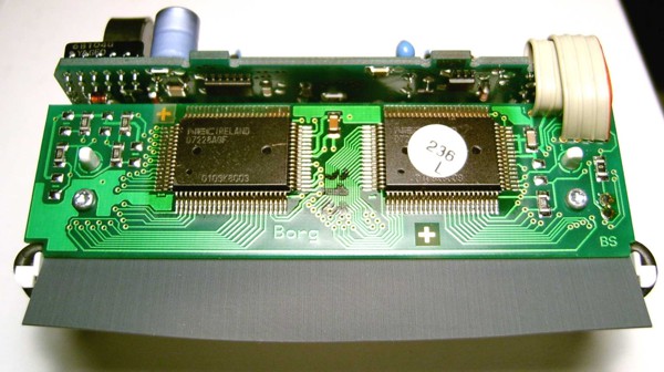
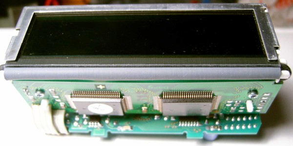
Disassembly is rather straightforward with the other four lugs on the housing (one in the center of the longer sides each, one on the shorter sides each). The internals look like this as they emerge from the housing:
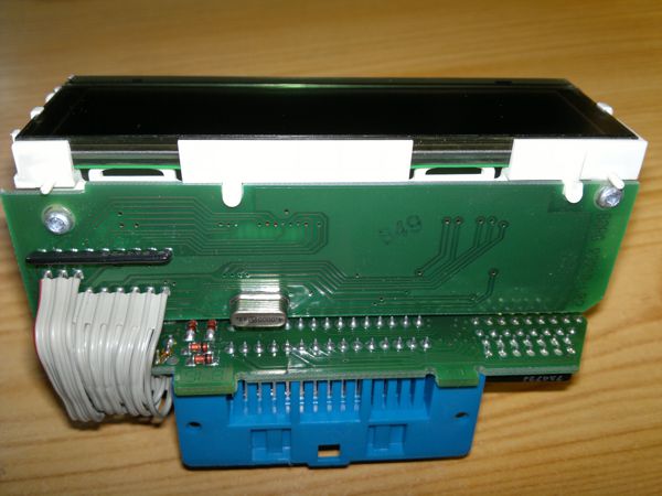
After removing the four miniature screws and carefully unfolding the printed circuit board, you can see the flexible panel that connects the display to the rest of the unit:
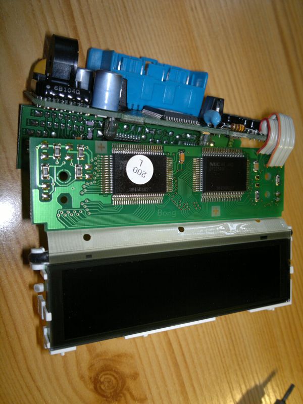
This flexible printed circuit board is the main culprit: the connection deteriorates and breaks over time. Also, while there is a rubber band just below the connecting surface pushing the flexible PCB and the display glass together, this rubber fatigues and loses its thickness, as well as its strength to force the connecting surfaces together. Note that if you remove the extra glass layers behind the display panel, note how they were fitted. If you put them back turned around, the readout will change from negative (dark background, lit letters) to positive (lit background, dark letters).
Originally, I tried to use the electrically conductive adhesive transfer tape manufactured by 3M under the designation 9703. This is the professional glue that is supposed to hold such flexible PCB cables together, not some DIY fix. It's only conductive in the z-axis (across the tape, between the adhesive surfaces, that is). It's made from very small conductive particles carefully organized in this direction, meaning that no matter what connectors and connector gaps are used, it will only connect the precisely opposing connectors. Because some very popular electronic gadgets, namely iPods, suffer from practically the same display-flexible panel separation problem, some people make a few bucks by buying the tape (it comes in 30-meter rolls), cutting it to small pieces and selling it on eBay and similar.
It's not a bad solution but there is an even better one. Instead of a thinner adhesive, you can use a so-called zebra connector, although not the thick, rigid one that connects immediately opposing connector but the one in sheet form, that can connect more remote connectors. If you examine the original flexible PCB, you'll see that it does nothing else but connects the exactly opposite pins of the edge connector and the display connector. The sheet connector does the same. I bought mine from Club Generation XM in France but you can just Google for the French name "nappe afficheur gauche citroen xm" and you'll find people selling it.
Remove the original flexible cable carefully. If yours still sticks to its original position, attack one end, it will peel off all right and leave quite a lot of residue. Clean the residue. I mean it. Really clean it. The success of the operation depends on it. Use acetone (nail polish remover, but note that there are "modern" ones without acetone now, read the label. Also try to find one with the minimum amount of perfumes and other stuff. Pure acetone is best, of course) or alcohol. You have to remove all traces of the glue, the PCB edge connector should be clean and copper-colored everywhere, the LCD display connector edge should be clean and transparent as glass (the actual connectors are almost invisible there, you might see something with strong lighting). Use ear picks and be patient, even if it seems to stay there at first, it will clean off in a few minutes. Don't skimp on that; you have been warned.
Assemble most of the unit but don't fully fasten the screws on this side. Slip the conductive rubber beneath the PCB. You can peek into the slot below and see if it protrudes from below the white display holder assembly: it shouldn't. Make sure the rubber is aligned and perpendicular (simply measure the protrusion, it should be equal at both ends) and carefully move it with tweezers if necessary. You might find it easier to fix the rubber to the display holder with a small pieve of Scotch Magic Tape first so that it doesn't move while you fasten the screws.
The rubber has no adhesive, it's simply thicker than the original flexible PCB and the screws will hold it together beautifully.
Bend it down carefully (not sharply!) and place the display unit over the rubber. No glue here, either, it simply sits into the recess of the display connector. Replace the display carefully and push it back into the housing. It will be a tighter fit, probably, than it was before, and this is a good sign: this extra force will make sure the contacts are perfect.
Assemble everything and enjoy: