Switches with LEDs
The XM Series 1 was born in the era of automotive bulbs. When it came to the Series 2, LEDs were already entering the scene. New switches like those on the dashboard started to come with LED illumination but earlier switches retained (and shared with other Citroëns of the time) remained with plain old bulbs in many switches of the door windows, electric seats or some center console switches. Retrofitting LEDs to these is a simple process with huge benefits: longevity (practically, eternity) of the LED, cool operation temperatures and lower power consumption are all welcome changes.
Window and electric seat switches
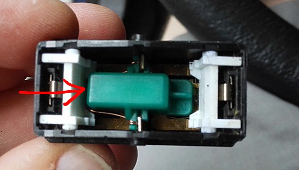
The bulb holders inside the switches are not huge, they are only large enough to house a small socketless bulb:
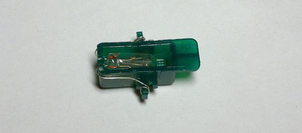
Using traditional (through hole) electronic components, although possible, is a very tight fit. The LED itself can take the place of the bulb but the compulsory series resistor has to be housed outside the holder, with care taken not to obstruct the operation of the switch. And even then, the positioning of the LED is not optimal: bulbs are not directional but LEDs are and placing them horizontally, as the holder recess allows it, will not direct its light at the switch surface. Note that you need green light LEDs, not white. White will illuminate, too, but the colors will be washed out, green is much better.
Smaller, SMD components are better here, but at the expense of more skill required to handle them. It really helps if you have a helping hand stand with a magnifying glass.
The SMD components should be of size 1206 imperial (3216 metric, this actually denotes the physical size, 3.2 by 1.6 mm). Window switches have a separating plate in the middle of the cap, shadowing the illumination of the opposite arrow, so it's best to place an even number of LEDs into the holder. The 1206 components fit easily into the holder, with some room to spare but a resistor of this size can only handle 0.25 Watts and we would need slightly more. The first thought would be to use a 1210 format resistor but there is a better solution: two resistors in parallel. The main advantage is that resistors come with resistance in specific, standarized steps and using two makes it easier to fine tune the necessary resistance still using common, run-of-the-mill values.
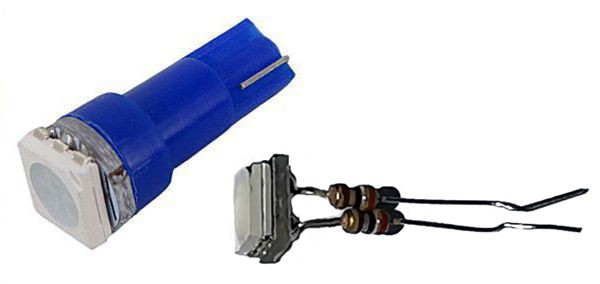
The original version I suggested earlier had the components soldered together, with wires attached to the ends:
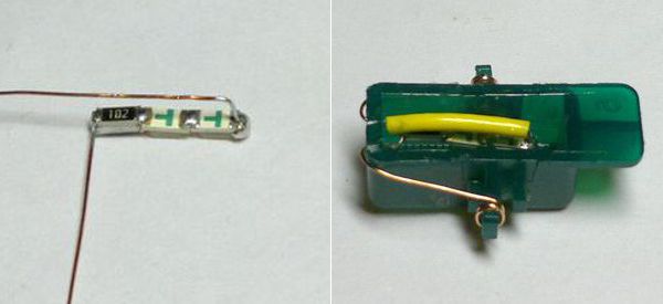
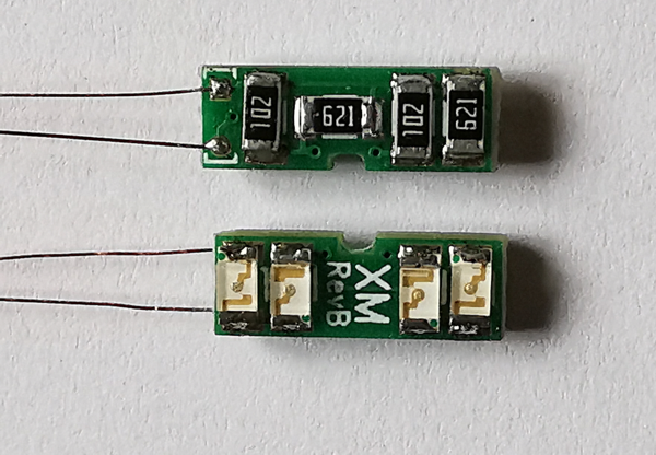
Not bad but we can do better than that. With all the experience gained in LEDs Everywhere, I came up with a better idea. Instead of attaching these components end to end with tedious work, a small PCB can hold them much better, is easier to solder and with careful packing, has room for twice as many LEDs:
But first, you have to know the electronic details of the LED you use in order to calculate the resistor values. Two pieces of information are important from the supplier catalog or the component datasheet: forward voltage (Uf) and forward current (If). The resistor value is easy to calculate:
R = (Us – 2Uf) / If
where Us is the board voltage, 14 V to be safe (the nominal voltage of 12 V lead batteries is actually 13.8 V, anyway). If we take an example of Uf = 3.1 V and If = 20 mA (the Foryard FYLS-1206PGC LED I used) the resistor will be (14 V – 6.2 V) / 20 mA = 390 Ω.
This is where the parallel resistors come in handy. Although you could buy 390 Ω SMD resistors for sure, such uncommon values might not be that readily available. These SMD components leave the factory on reels of 4,000 components. Just as an example, in the store I buy my components from, bog standard values can be bought in any quantity, they always have reels available and cut off as many components as you wish. With uncommon values, you might be forced to buy in larger quantities or maybe per reel because they probably won't be able to sell the rest that easily.
Just a reminder, you calculate the common resistance as:
R = (R1· R2) / (R1 + R2)
Two very common usual standard resistor values, 1 kΩ and 620 Ω give us just what we need (differences of a few Ohms aren't important): (1000 · 620) / (1000 + 620) = 382.7 Ω.
Board
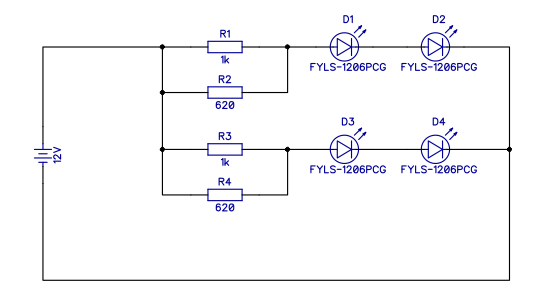
A schematic diagram is hardly necessary, all we need is two serial LEDs fed from two parallel resistors.
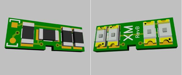
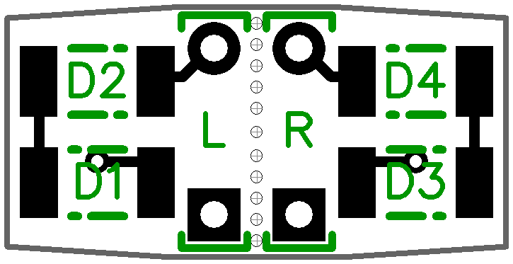
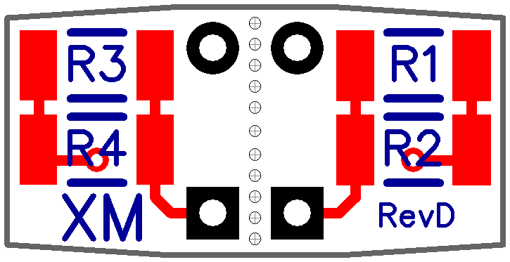
The printed circuit board layout (Gerber files are available if you want to have them produced):
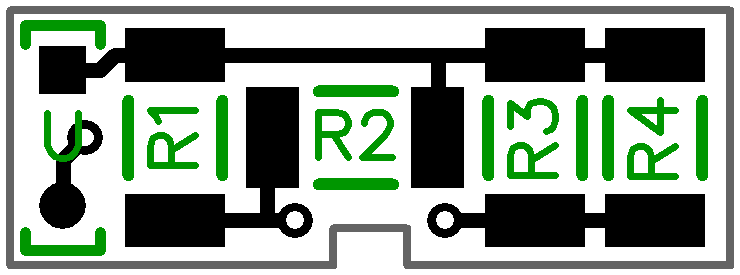

So, if you use the same (or equivalent) LEDs as I did, the components needed will be as follows. With different chips, modify the resistors accordingly:
| Position number | Window switch | Seat switch |
|---|---|---|
| R1 | 1K0 | 1K0 |
| R2 | 620R | 620R |
| R3 | 1K0 | — |
| R4 | 620R | — |
| D1 | FYLS-1602PCG | FYLS-1602PCG |
| D2 | FYLS-1602PCG | FYLS-1602PCG |
| D3 | FYLS-1602PCG | — |
| D4 | FYLS-1602PCG | — |
Soldering
Soldering SMD components is a challenge, especially if you only have a regular soldering iron and eyesight. Using a helping hand stand with magnifying glass or head magnifier glasses helps a lot. The usual way would be to use hot air rather than a conventional iron and a soldering paste that is tacky enough to hold the small components in place until you solder them. But you can still do it if you only have the regular equipment. Have a pointy iron tip, and buy two extra items: a flux pen and a desoldering wick. Flux pens are made under many brands, they look like a thick marker pen, have an alcohol or water soluble flux fluid coming through the tip. Don't think you can skimp on this; with through hole components, it was OK to use the flux (usually resin) in the solder core. But you won't solder SMD parts without a flux, believe me. This is what makes it work.
The desoldering wick is a simple braided copper wire that, due to its capillary action, sucks up unused solder like a sponge. Because you will add more solder than needed in many spots, the wick makes it possible to remove the unnecessary extra. Find a thin one (1 mm or less in diameter) because when you use it, you need to heat the wick and a thicker version will require too much heat.
The best way to solder SMD components that I could find on the Net and can verify by my own experience is as follows:
1. Tin one pad of the component you want to solder. If the PCB has been tinned in manufacture, there is no need for flux here. Just make sure there is a small bump of tin on that pad (practice will teach you how much but really not much).
2. Apply flux onto that tin now.
3. Place the component on its pads. It won't lie completely flat because of the tin on one pad. Clean the tip of you iron: there's no need for extra solder at all. Carefully pushing the component down in place with a forceps or needle-nose pliers (as you prefer) heat the end lying on the tinned pad. As soon as the pad gets hot enough, the solder will melt, the flux will do its job, the component will sink into its flat position and it will be soldered in place all right.
4. Now turn over, apply flux to the other pad and component end.
5. With a very small amount of solder on the tip of your iron (practice will teach you how much, really small), heat the other end. The flux will do its job once more, this end will be soldered in place, too.
With enough practice, that's all there is to it. If the blob of solder is too large, remove it with the wick, apply flux and heat again with a smaller amount of solder (if any) on your tip than before. Use a strong magnifying glass (25x to 30x) to look around closely.
The PCB itself can be held still with Scotch or applying double-sided adhesive to your work area and pushing it into the adhesive (you can also use a stretch of Scotch tape upside down, fixed in the end with normally positioned tape). A piece of glass can serve as a perfect work area (I always use an old BX mirror plate). Solder doesn't stick to it and you can apply and removes adhesive tapes with ease.
Always think about the order of components before you start. In our case, the R2 resistor needs to be soldered first because once its neighbors are in place, it would be much harder to reach its terminals with the iron. The rest isn't important with this particular PCB. Follow the markings on the board with polarized components like LEDs (the dotted end of the contour lines denote the orientation of the terminal marked with a small dot on the LED).
You'll also need wire connections (use a multi-stranded wire, remove the insulation and use the individual strands):
1. Tin the pad you want to connect to. Tin the end of the wire.
2. Apply flux.
3. Solder the wire end to the pad in one go.
Soldering, act two
Having said all that, using the "correct" method of soldering SMD parts is with a hot air gun. It's much easier, much faster, much more comfortable and much more fun, so really consider it if possible. Basically, instead of traditional solder, you use soldering paste, a mix of very tiny solder droplets in a tacky flux glue.
1. You just apply a small amount of solder paste onto the pad. I found the paste-in-a-syringe to be the easiest to use, you can very easily put small amounts of paste to the PCB surface. You don't need flux, you don't need tinning, just paste straight on the pad (a little blob in the middle, about covering just about half of the pad of these PCBs, there's no need for more). If the tip of the syringe starts to clog up (the paste tends to dry out when left exposed for longer periods), you can gently, very gently warm up the tip to make it flow again easily.
2. When both pads have the paste, simply place the component, press it into the paste with tweezers. The paste is a glue, the component will stay there. Again, you don't have to apply flux, just push the component into the paste.
3. Heat the component, both ends, using the hot air gun (250 °C is just fine with the usual soldering paste). You just move the tip of the gun here and there to heat both sides. When the solder paste melts on both sides, it will turn into regularly looking, shiny metal solder and now the magic happens. If the paste blobs at both terminals of the component are hot enough to flow, surface tension will literally move the component, it will align itself automagically with the pads, jumping into the perfect position–it's really fun to watch.
For the soldering itself, you don't even need flux but it helps to have it handy if you're not completely satisfied with the positioning or the amount of solder applied. Reheating and resoldering is easier and results in better finish if you add a bit of flux for each reheating operation.
However, soldering the connecting wires at the end is still easier with the regular iron.
Assembly
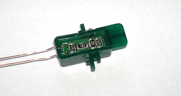
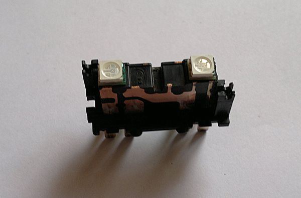
As soon as you have all components and the two connecting wires (length: 38 mm, diameter: 0.3 mm or similar) soldered, you can start assembling. Hold the board with the black resistors facing upwards, the wires to the left:
Have your green bulb holder with the opening facing up, flat part to the right and thread the two wires through the holes in the left side wall of the holder. Yes, I know, it's not that easy; still, it can be done. Use tweezers and a magnifying glass. If you're desperate, enlarge the slots leading to the holes (I don't recommend forcing the wires down the original slots, the wires are thin and the soldering might also let go) with an Exacto knife or similar:
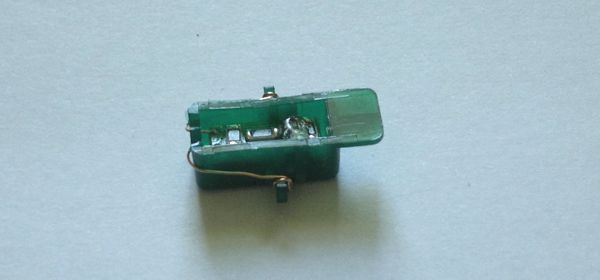
At any rate, you need the board inside the holder, LEDs facing down (into the closed part of the holder), wires sticking out from the left wall holes. Route the wires to the sides and wrap them around the pegs twice. Cut the excess wire. Although the key in the green holder and the notch in the PCB, as well as its wire will probably keep the board in place, you might want to add just a blob of hotmelt glue in the end to make sure the board never wants to peek outside any more.
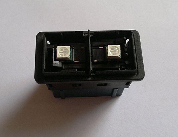
With the switch (be it either window or electric seat switch) in your hand, hold it in the way shown on the picture, the separated wall on the bottom connector upwards:
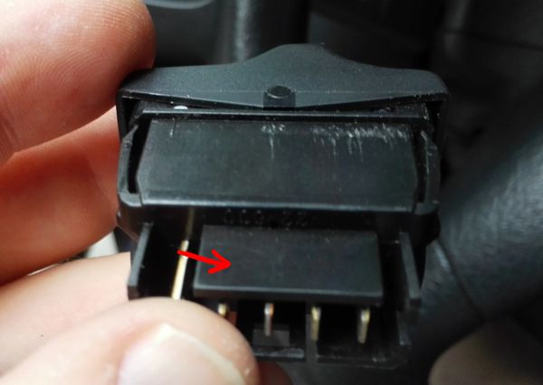
While you do so, note which side of the switch is to your left:
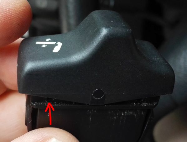
On the seat switch it will be obvious because this is where the symbol is but the window switch is two-sided. In either case, make sure you put the green holder with its non-flat, illuminated side rotated to the left side of the switch as you determined:
If you fail to do so, there will be no light: the LEDs are sensitive to polarity by their very nature.
One-touch driver's window
This switch requires a different angle of attack. Remove the caps (the inner part is just like the regular window switches, the outer parts can be prised off with a small screwdriver; keep it parallel to the switch surface and try to prise the side closer to the center of the switch). The center operating flaps just slide out and remove the rubber seal carefully. The bulbs are wedged into the slots of the connector plate. Cut out the bulb, leaving as much of the wires as possible. If you happen to remove the wires, there is no way to push new ones into their places (in this case, the only alternative is to solder new wires onto the connector plates. Not impossible but requires a relative hot iron (around 450 degrees Celsius) and, consequently, very skilled, very quick and very careful soldering so that nothing plastic will be damaged). Leave the wires, it's better that way.
Just like with the main switches, I now started to think about using the same PCB-based route instead of components soldered directly in situ.

This small PCB will be held in place by the bulb wires (or replacement wires you soldered there), preferably use up to 0.6 mm to make it more rigid). Again, as with the other switches, the board hosts more LEDs than the older approach could handle.
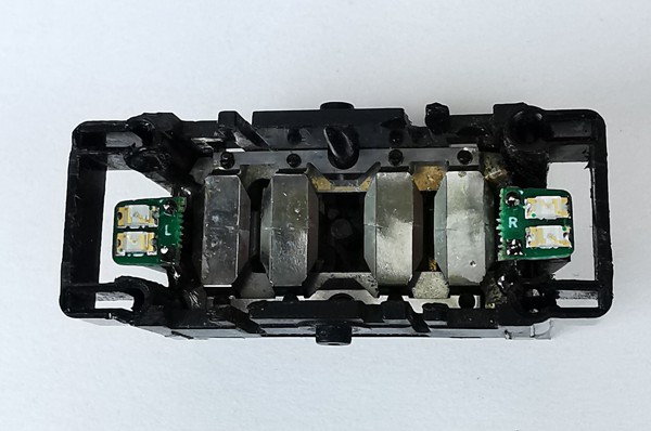
This is actually a double board, not a single one. After having soldered the components, it has to be snapped in the middle and the halves soldered to the left and right side of the switch, as marked on the PCBs. The lab I have my boards produced by couldn't put a so-called V-cut onto such small a board, hence the row of small holes to make it still possible to break the board into two halves. A V-cut is a small groove scored into both sides of the board to, similarly, make it easy to snap and this is the usual approach with larger boards that need to be separated.
Now hold the switch so that the plastic frame around the pins has the missing side at the bottom:
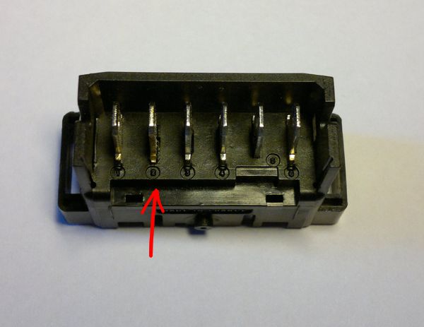
If you turn the switch around, still the missing side at the bottom, connect the two boards as indicated by the L and R markings. The LEDs will, obviously, face upwards.
Careful with the iron, try not to melt the plastic of the switch.
Center console switches
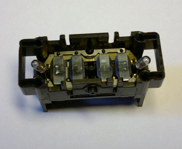
The switches in the center console (rear windows, rear windows disable, electric armrest) have a different bulb inside, not that green holder. The bulb is cylindrical, with a diameter of 4.2 mm and its terminals are soldered into a PCB at the bottom of the switch. The rear windows disable switch already has a LED for the yellow light position.
You can either buy component LEDs and the necessary series resistors or use the T5 bulbs described in LEDs Everyhere. In the second case, you need to disassemble them (straighten the wire terminals and pull out the internals from the colored plastic holder). These are LED chips with usually two small resistors attached to both ends and fit very nicely in the place of the original bulb. Having two resistors instead of one (obviously, with both half the value of the required resistance) has a real advantage: as the voltage drop is only half on each resistor, they can be of 1/8 W instead of 1/4 W, giving a smaller resistor. Even if there are two of them, they fit very nicely.
You'll probably find these 5050 chips to be much too bright. Simply replace the resistors with larger values (remembering that our brightness perception is logarithmic, so double the value isn't half the brightness). In my case, and that's about typical with 5050 chips, I needed to go up to 2 × 3.3 kΩ (that's approximately ten times larger than the usual ≈600 Ω of 20 mA LED chips). Or, if you use component LEDs, you have to experiment with your required brigtness level, anyway.
Note the polarity before you solder. The easiest way to keep track of polarity is to place a little mark on the PCB with permanent marker. Positive feed comes in at connector A1 of the window disable switch and A5 for all the other center console switches. With component LEDs, make sure the dome of the LED protrudes somewhat from the switch body, otherwise the illumination will be too centered in a hotspot. You might need to make some tests but as a rule of thumb, at least the domed part of the plastic case should protrude, or maybe even a bit more. The 5050 chips with their PCB holder sit very snugly on top of the switch body, in a small recess there, giving a relatively large angle of distribution, so I finally voted for them.
In the case of the yellow LEDs of the disable switches, I simply replaced them with current, brighter yellow LEDs without any further modification.
Dashboard switches
The switches in the dashboard row (foglights, hazard, heated window, etc plus the rear wiper and washer) have LEDs from the factory, however, technology back then only allowed much dimmer LED chips than today. If all your other switches are brought to current illumination levels, you might want to replace those LEDs as well. You need to buy 3 mm component LEDs, around 150-300 mcd (green is always much brighter, test your sortiment before you decide). All switch caps have a green symbol and a yellow filter for the operation telltale, although the hazard switch has a red LED behind it. If you prefer, you can replace some or all of the other yellow LEDs with red ones (in the end, I changed the rear window heater and rear foglight switch telltale to red instead of yellow. I always had to think about momentarily which foglight is which; with yellow telltale to the front and red to the back, it comes intuitively now).
Dismantling is easy, you don't need to take the whole switch apart. Prise free the cap and you'll find a plastic part serving as a reflector for the two LEDs. You can prise its lugs free (one at the top, two at the bottom). The small PCB with the LEDs can be removed carefully, use a needle nosed pilers to grab the LED terminals. Snug fit but it can be removed: it sits on prongs protruding from the internals below, serving as connectors. Once you have the PCB out, there's no need for more disassembly. Note the polarity of the LEDs (there are switches with the same PCB but don't rely on it, check every single one yourself).
The SMD series resistor is on the back of the PCB, 562 Ω, approximately correct for the typical 2.2 V and 20 mA LEDs. Desolder, bend the new LED terminals outwards (mimicking the original), make sure the domed part protrudes from the reflector holder (I found it better when it protrudes more than the original but that depends on your actual LEDs). Refit carefully, take care of not bending the connector prongs it sits on.
If the brightness is too much (it probably will be), consider replacing the resistor mentioned above. Because my LEDs were quite bright, I had to go to as high as 6.8 kΩ to get the result I wanted.
Rearview mirror switch
This switch has a single LED soldered in the middle. If you're satisfied with the brigtness, there's nothing to do. If you need somewhat more, just replace it with a contemporary green LEDs (probably greener, the original is somewhat yellowish). Just bend the terminals like the original LED was (quite rudimentary for a solution, all the other switches are better designed, but it works).
Anti-theft keypad
Again, only start to work on it if you're not satisfied with the brigtness. The keypad background is done with tungstens in a very special holder, so unless you have a complete replacement keypad to play with, it's unlikely to be worth trying to replace those. The LEDs, however, are very nicely designed, in a push fit socket, no need for soldering. Just remove the LED, observe the dimples on the terminals and use a needle nose pliers to make similar ones on the new LEDs. Both color and polarity are correctly marked on the PCB, there's no need to worry about that. The original LEDs are 5 mm but I found that the 3 mm ones I used all around are just fine and illuminate their front panel hole perfectly. The color is nicer for my new green LED and the red one, also serving as an alarm warning, is considerably brighter now.
End results
These pictures were taken an hour before sunset, the switches jut shaded by hand. They start to become visible to the naked eye around this time of day, the window switches being close to the window are not yet really glowing but the seat switches are nice green already:
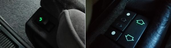
In pitch darkness:
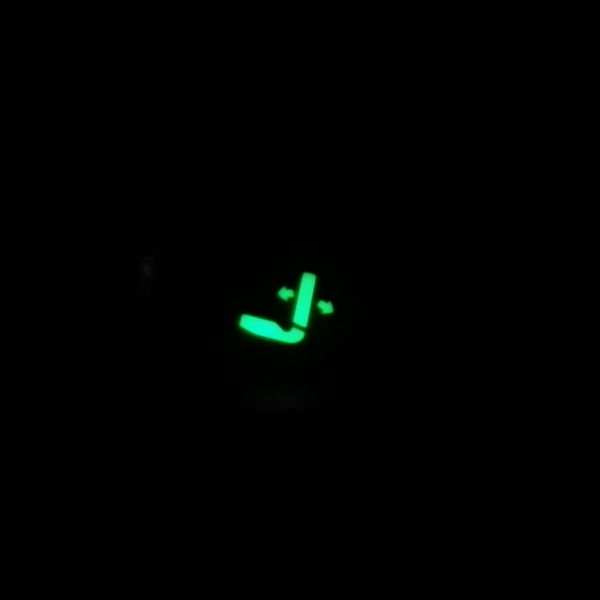
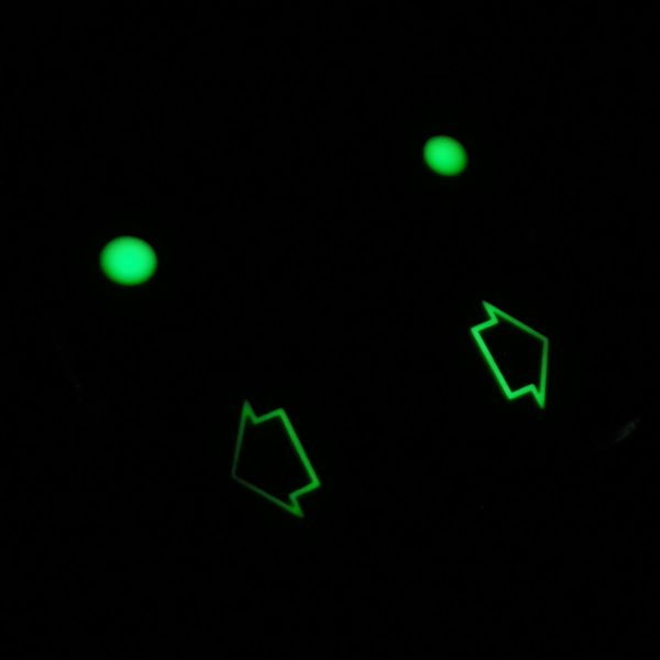
As you can see from the switch photo above, the green holder isn't symmetrical and the lighting will be offset to one side, hence the difference in the two arrows. A solution could be to modify the holder a bit: namely, to file or cut half of the green material covering the side farther from its arrow to illuminate. This might result in a slightly different tint for the two arrows but our eyes are more sensitive to the brightness here than the colour difference. But if you don't mind the extra light, you can remove the green material completely, leaving all LEDs exposed. I tried both and I like my switches not only to faintly glow in the dark but to give a nice green light, so I decided on complete removal but you have to experiment for yourself. The holder material is much tougher than one would think but with a good Stanley knife or a coarse file and with a little perseverence it can be done.