Fuel injection basics
Citroën used various systems of two manufacturers, Bosch and Magneti Marelli. All those systems operate on very similar principles so troubleshooting them involves more or less the same steps.
There are two basic categories: fuel injection (EFI) and engine management (EMS). EFI systems, as their name implies, are responsible for the injection of fuel only, the ignition sparks are created using traditional methods (a breakerless distributor). EMS systems, in contrast, govern both fuel injection and ignition themselves.
The fuel injection itself can be divided into two further categories: multipoint (where each cylinder has its own injector, although they all operate simultaneously, just in front of the corresponding inlet valve in the manifold) or monopoint (a single injector located before the throttle valve serves all cylinders).
Although the number of injection systems might seem frightening at first sight, all these systems are basically similar to each other, so diagnosing and troubleshooting them is not that different.
The fuel is drawn from the tank by a continuously operating fuel pump, transported via a filter to the injectors, then back to the tank. There is a pressure regulator in the circuit as well to keep the pressure of the fuel at a constant pressure above that in the inlet manifold. As the pressure difference between the two sides of the injectors are constant, the amount of fuel injected depends solely on the opening time of the injectors. The injectors and the regulator sit on a fuel rail on top of the engine in multipoint systems while they are combined into one unit in monopoint systems.
The injectors are solenoid valves that, when open, let the fuel from the supply enter the inlet manifold, directed onto the back of the inlet valve of the corresponding cylinder (multipoint) or into the air inlet still before the throttle butterfly (monopoint) as a finely atomised fuel spray. Either monopoint or multipoint, the ECU calculates half of the required fuel per engine cycle and injects it at each engine revolution, that is, twice per cycle.
The amount of fuel to be injected as well as the exact time of generating the sparks are calculated by the electronic control unit (ECU). The usual term is "calculating" but this is nothing more complicated than a lookup in a stored table. You can visualize this easily as a large table with rows and columns. For instance, rows might represent various engine speed values while columns might denote the various values of engine load (roughly speaking, the position of the throttle pedal). The cell where a given row (rpm) and column (load) intersects might contain the amount of fuel to be injected under the given conditions. However, this value from the table only gives the starting value which the ECU will modify according to many signals coming from the various sensors.
Such tables store precalculated return values corresponding to given input signals. And as they are implemented in programmable ROMs, hence the possibility for chip tuning: replacing the tables with carefully modified ones can yield different engine behavior, including performance, acceleration, fuel consumption and emission.
EFI systems
The two main inputs of the EFI ECUs are the ignition (the signal coming from the distributor) and the actual engine load (represented by the amount of air sucked in by the engine). The ignition pulses, having entered the ECU, go through a shaping and halving circuit that forms regular square pulses whose frequency is half of the ignition frequency. The required amount of fuel will be injected in two installments. This signal serves as the time base for the injectors and the frequency remains unchanged throughout the whole calculation.
The width of the individual square pulses are calculated (or, as we already explained, looked up in a stored table) based on engine speed (the ignition frequency) and engine load (the amount of air sucked in by the engine). For the purpose of measuring this second, different sensors can be used. Earlier systems (Bosch Jetronic) used an air flow sensor (AFS): as air flows through the sensor, it deflects a flap, which is connected to a potentiometer. In consequence, the resistance of the meter is proportional to the amount of air passing through it. Later systems (both from Bosch and Magneti Marelli) used a manifold absolute pressure (MAP) sensor instead, which functions as a simple pressure sender (just like the oil pressure sensor in the engine).
Simpler EFI systems—the Bosch Mono-Jetronic fitted to later 1380 ccm engines—do not use any engine load measurement at all. To reduce the number of components and the costs, these systems rely on the position of the throttle pedal as a subsitute input. This is less accurate than actually measuring the quantity of air entering the engine, but it is much simpler.
Using these two main input signals the ECU determines the base pulse width (tp). This square pulse signal would be enough to control the engine under ideal conditions. However, the operating circumstances of an egine are seldom so favorable, hence, the ECU must carry out additional calculations to modify the base pulse width according to some special requirements.
The first major real life factor is the temperature of the air entering the engine. The cooler the air is, the denser it becomes. To compensate for this difference, the AFS housing incorporates an air temperature sensor (ATS) as well. MAP-based systems use a standalone sensor—depending on its location it might measure the temperature of either pure air or air-fuel mixture. Based on the values obtained from this sensor, the ECU might decide to lengthen the pulse width to allow more fuel, a richer mixture to enter the egine.
Similarly, extreme operating conditions such as idling or full load operation require a richer fuel mixture. The throttle position switch or potentiometer (TS/TP) informs the ECU whether the throttle pedal is fully depressed, fully released or somewhere in a middle position.
Starting the engine in cold weather is an even more special situation. Part of the fuel becomes condensed on the cold engine parts, consequently, a richer mixture is required to start the engine. The ECU monitors both the position of the ignition key switch and the coolant temperature sensor (CTS). If the CTS indicates that the coolant fluid is hot—in other words, a warm start—, there is no need for the longer injection periods.
As soon as the ignition key returns to the normal position, the ECU starts a 30-second warm-up period. In the first second, the ECU adds about 50% of the normal amount of fuel. Until the end of this initial warm-up period, this surplus drops to around 25%. From that point, the fuel surplus is determined by the temperature of the warming engine, as dictated by the CTS. To stabilize the idle speed in a Jetronic-controlled engine still cold, the throttle is bypassed through an auxiliary air valve (AAV). This valve is fully open when the engine is still cold but as the temperature rises it starts to close. On a warm engine it blocks the bypass completely. The air going through the bypass is measured by the AFS, thus it tricks the ECU into providing more fuel. This device is heated electrically, hence, it will close after some time no matter what temperature the coolant has.
Later systems have a similar bypass around the throttle butterfly but instead of a simple mechanical valve, they use an electrically operated solenoid valve controlled by the ECU to decide the amount of air which is allowed to bypass the butterfly.
All these additional correction factors—air temperature, idle or full load, starting, warming up—sum up into an additional pulse width (tm). But we've not done yet. The operation of the injector solenoids depend heavily on the battery voltage fed to them. To compensate for lower voltages, the injection time period must be lengthened by ts.
The total pluse width (also called injector duty cycle) is calculated by summing up the three values we received, the base width, the various correction factors and the voltage correction: ti = tp + tm + ts.
If the revolution is above a specified limit (around 1,200 per minute) and the throttle is closed—this is called deceleration—, the momentum of the car is sufficient to rotate the engine through the roadwheels. To save fuel, the injection is cut off. As soon as the engine speed drops below the limit or the throttle is opened, the injection is reintroduced.
Finally, to avoid prolonged operation at revolutions exceeding the specification of the engine, the injection is cut off above a maximum engine speed (6,000-7,000 rpm, depending on the engine).
 Models equiped with a catalytic converter use an oxygen sensor (also called lambda sensor) to measure the oxygen content of the exhaust gas to adjust the fuel mixture to achieve the ideal lambda ratio.
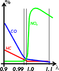
Theoretically, the mixture burned in the engine should contain air and fuel in proportion of 14.7 parts to 1 to achieve ideal combustion. The lambda ratio is simply the proportion of the actual mixture to the ideal. A lambda value of 1 means ideal mixture, values below 1 mean rich, those above 1 lean. By measuring the oxygen content in the exhaust gas the computer can decide how to adjust the mixture to keep the lambda value around 1. The main reason for this is the catalyst, whose efficiency depends heavily on the lambda ratio of the gas fed to it. If the lambda is just a fraction below 1, the CO emission rises sharply, and a little over 1 skyrockets the NOx emission. During cold start, acceleration or full throttle the computer decides on a different mixture but under normal operating conditions it sticks to 1, provided that everything else in the system works well. The sensor does not start working until it reaches the temperature of 350 °C.
Actually, this is the reason of the higher fuel consumption of cars equipped with a converter. Lambda 1 is ideal for the converter and is also ideal from a scientific point of view, however, it is certainly not ideal when speaking about fuel economy or driving dynamics.
There is a final safety circuit in the system. During a crash, when the engine has already stopped, the fuel squirting from the injection system could easily cause fire. Hence, the relay of the injectors is controlled by the ECU, allowing fuel injection only when the ignition signal is present.
All systems—with the exception of Jetronic—have self diagnostic subsystems which constantly monitor the signals from the engine sensors and, should a fault be present, log an error code in an internal memory. More serious errors light up the warning lamp on the dashboard as well to inform the driver of the failure. The error codes can be extracted by either a special diagnostic tool or using a simple algorithm. Whenever the ECU senses the failure of a minor sensor, it omits the signals coming from that sensor and substitutes a fixed default value. This value is characteristic of a hot engine, therefore, cold starting and the warm-up period may be less than satisfactory, however, in normal operating conditions the engine may actually run quite well.
Most systems can also adapt themselves to changing operating characteristics or engine wear. If some of the components have been renewed, the ECU should be re-calibrated, that is, allowed to repeat its learning process. Disconnect the ECU multi-connector for approximately 15 minutes (with the ignition off, this is extremely important!), during which time the ECU resets to the default values. Reconnect the connector and run the engine until it reaches the normal operating temperature.
EMS systems
The fuel injection subsystem of EMS systems works as we have already described in the previous section. The only significant difference is that these systems generate the ignition signals themselves, so they cannot at the same time rely on these signals as input. Instead of the signal coming from a distributor, they use a crank angle sensor (CAS), an inductive magnet mounted in proximity to the flywheel which has steel pins set into its periphery. As the flywheel rotates, the CAS senses its rotation through the magnetic field. The sensor also informs the ECU of the top dead center (TDC) position of the engine (two of the pins are omitted at the appropriate locations and this results in an output signal variance the ECU can read).
The rest is the same: the base pulse width tp is calculated based on the CAS and AFS/MAP sensors. The correction factors—air temperature, idle or full load, starting, warming up—based on the sensors ATS, CTS, TS sum up into an additional pulse width of tm. The battery voltage is also taken into account as a correction factor ts.
Besides, the same input signals (AFS, CAS, CTS and TS/TP) are used for another calculation (or lookup in a table), yielding the correct dwell time and timing advance for the ignition. The dwell period remains rather constant but the duty cycle varies with the chaging engine speed. The ignition signal is amplified and sent to a distributor containing only secondary HT components: it does not create the ignition signal only routes the HT current to each spark plug in firing order.
Some systems also have a knock sensor (KS), sensing the engine vibration associated with pre-ignition ("pinking"). If this occurs, the ignition timing is retarded to avoid engine damage.
All EMS systems use some form of an ECU-controlled idle speed actuator in the bypass around the throttle butterfly—either an idle speed control valve (ISCV) or an idle control stepper motor (ICSM). The second is not a solenoid valve but a stepper motor that can control the bypass opening more precisely. In case of a simpler valve, the ignition timing is slightly advanced or retarded to fine tune the idle speed under all—cold and hot—operating conditions, even if an electric load (headlights or fan) is switched on abruptly.