Testing the EFI & EMS components
There are basically two electrical measurements used in testing the various components. Voltage tests should be carried out with the ECU connector connected (unless otherwise stated in the test description). The cleanest method is to use a Break Out Box (or BOB), which is an extension connector placed between the ECU connector and its plug, making the various terminals accessible for measurements. If no BOB is available, use backprobing: peel back the insulating boot from the plug and attach the probe to the relevant pin.
![]() Never disconnect or reconnect the ECU connector with the ignition on. When using a voltmeter to test the various components always make sure that the impedance of the meter exceeds 10 Mohm, otherwise the ECU might be damaged!
Never disconnect or reconnect the ECU connector with the ignition on. When using a voltmeter to test the various components always make sure that the impedance of the meter exceeds 10 Mohm, otherwise the ECU might be damaged!
In all test procedures described we mention the terminal numbers of the sensors and other parts involved. However, to spare unnecessary measurements, it is always advisable to start the testing on the corresponding ECU pins (those are given in the accompanying tables for all possible ECU variants). If what you measure there comforms to the values specified, no further testing is required. If not, repeat the measurement on the sensor or part itself. If you receive the correct values this time, the wiring back to the ECU is suspect. If not, the sensor is faulty.
Some sensors can be checked with a simple multimeter, but to track down more complicated failures in a system constantly adapting to changing circumstances an oscilloscope might be essential. Some sensors produce signals that change too quickly to follow them with a simple digital meter or the waveforms themselves might be essential to judge their correct functioning. There are handheld digital oscilloscopes (or graphical multimeters) available now; they look much like the usual multimeters but their display is larger in order to present graphs in addition to digits. Although the resolution of the display might be rather coarse when compared to a traditional CRT laboratory oscilloscope, they are very convenient to use around the car, especially as they usually are storage oscilloscopes: they can record data and play it back later. With this feature, you can analyse signals which change too quickly for a real time evaluation. Such an oscilloscope and the test procedures described here are enough to find any failure in the system—those fancy diagnostic computers used at the dealer garages are essentially the same. Their advantage is that they measure many circuits at the same time and are capable of comparing the values and waveforms obtained to stored patterns, notifying the repairer of the failure directly. Although this is comfortable and fast, they cannot do more than you can with the necessary equipment and patience.
The Jetronic system uses the board voltage to feed the sensors. In contrast to this, the Motronic ECU supplies a stable 5 V reference voltage to its sensors. Thus, the voltage levels are different in the two systems although resistance values are generally the same.
Checking for satisfactory earth can be accomplished by a simple voltage test: attach the positive probe to the reference terminal and the negative probe to the earth or return terminal in question. If the earth is satisfactory, the meter indicates the supply voltage. A difference of up to 0.25 V is generally accepted as a reasonably good earth.
For resistance tests ensure that the ignition is off and that the circuit or component under test is isolated from the rest of the system (in other words, its connectors should be disconnected). Failing to observe this might yield inaccurate results and even damage the ECU or the meter.
Repeated cranking of a non-runner engine may result in unburnt fuel passing into the exhaust system. If the car is equipped with a catalyst, the unburnt fuel collected in the converter might explode suddenly as soon as the temperature reaches a certain level. Such an explosion and the resulting high temperature can melt the internal parts of the catalyst which, apart from destroying the converter, may block the exhaust causing the loss of engine power. To avoid this kind of damage, complete each test quickly and allow the engine to run at a fast idle for at least 30 seconds between the tests in order to clear the exhaust system of any fuel residue.
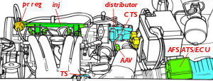
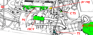
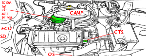
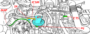
Location of components
- Bosch L/LE-Jetronic:
- Bosch Motronic 3.1:

- Bosch Motronic M1.3:

- Bosch Motronic ML4.1:
- Bosch Mono-Jetronic:
- Magneti Marelli G:
Auxiliary Air Valve (AAV)
| Term. | ECU pin | ||
|---|---|---|---|
| LE-J | MP3.1 | M1.3 | |
| 1 | +ve | +ve | +ve |
| 2 | GND | GND | GND |
Start with a cold engine. Remove the two rubber hoses (one is coming from the big air intake pipe between the AFS and the throttle body, the second goes back to the inlet manifold, passing beneath the oil filler. Place a flashlight behind the valve and observe it from the front (it's easier with a small mirror): the light should shine through a small opening. Reconnect the hoses, start the engine and warm it up to the operating temperature. Then remove the hoses again, and check the opening once more; it should be closed completely. If it is stuck in one position, remove it, clean and slightly lubricate the mechanism inside.
If the rubber hoses connecting the valve to the rest of the system are still young and tender, you can squeeze them together strongly with a pliers. With a warm engine, the engine speed shouldn't change. If it does, the air valve does not close properly.
The best checking method is to isolate the AAV completely from the rest of the injection system. In order to do this, you have to remove both the hose feeding the AAV and the returning one where they attach to the concertina hose or the inlet manifold. You also need to plug both orifices now uncovered. The best plug solution I found can be made of small piece of rubber hose of the required size. stuffed at one end to make it a plug. To stuff the hose, I cut a small part from the handle of a kitchen wooden spoon, pushed it into the end of the hose and made it airtight with a jubilee clip.
With the AAV thus isolated, the car will not run at idle, it will cut off. Either use the throttle to warm the engine up or replace the hoses with the plugs on an engine already warmed up—but due to the vicinity of hot components, you might prefer the first alternative...
Air Flow Sensor (AFS)
| Term. | ECU pin | |||
|---|---|---|---|---|
| LE-J | LE-J* | ML4.1 | M1.3 | |
| 2 | 7 | [2] | 7 | 7 |
| 3 | 5 | [3] | 9 | 12 |
| 4 | 8 | [4] | 6 | 26 |
| * ECU on top of AFS. | ||||
Terminal numbers in brackets represent the internal connections between the AFS and the ECU. Inspect the air trunking for splits or other damage. Remove the trunking and check that the flap operates smoothly and it does not stick. Check that the connectors are firmly connected and making good contact.
Leave the AFS connected and connect your oscilloscope or voltmeter to the following points: negative probe to either AFS terminal #4 or engine earth, positive probe to #2. Remove the air filter box. Turn the ignition on but don't start the engine yet. The meter should measure 0.2-0.3 V. Watch the voltage to smoothly increase and decrease up to a maximum of 4.0-4.5 V as you manually open and close the flap.
If the output voltage is heavily stepped or becomes zero, try to clean the wiper arm and the signal track. Careful bending of the wiper arm may restore a lost or unreliable contact. Measure the resistance between terminals #3 and #4: it should be 300-500 ohm, between #2 and #4 as follows: 10-200 ohm if the flap is fully closed, 1-2.5 kohm if fully open. Between terminals #2 and #3: 8-500 ohm if closed, 1-2.5 kohm if open. Use resistance checking only to reveal major contact problems, the actual functioning should be checked by measuring voltage.
If no signal voltage was obtained at the first measurement, first check—with the AFS plug not connected—for the reference 4.9-5.1 V at terminal #3. Then look for a good earth (max 0.25 V) on terminal #4. If both are OK, check the wiring between the AFS and the ECU. If any or both of them are absent, examine their wiring back to the ECU. If you found no problem with the wiring and the voltage supplies and earth connections to the ECU are all right, the ECU itself is suspect. If you found the nominal battery voltage (engine stopped: 12-13 V, cranking: 9-12 V, running: 13.8-14.8 V) instead of the specified ones, check for a short circuit to battery positive somewhere.
Finally, reconnect the AFS and the oscilloscope or voltmeter, check the AFS with the engine running. At idle speed the output voltage will be 0.75-1.5 V, at 2000 rpm 1.75-2.25 V, at 3000 rpm 2-2.5 V, during snap acceleration 3-4.5 V. If you have an oscilloscope, compare the waveforms.
The coil spring
The flap and the wiper arm rotates against a coil spring. If the adjustment of this spring gets messed up (this might happen if somebody is trying to repair it when it ain't broken, releases the retaining clip without caution and the spring spins down in an instant). There is no precise way to readjust it without a CO exhaust gas analyser, a dynamometer or at least lots of expertise. So, if you find yourself in this position, you probably won't be able to spare what a Bosch injection specialist will charge you for the readjustment (a replacement AFS from a salvage yard might be cheaper).
However, you can adjust it at least coarsely the following way (provided everything else is functioning correctly, ignition OK, air filter clean, no vacuum leaks in the air inlet system): find a similar car. Remove both plastic covers of the AFSs by levering them off carefully. Attach a simple spring to the wiper arm of the correctly adjusted AFS and pull the flap open. Measure the expanded length of the spring and adjust the wrong AFS so that its flap would require the same amount of force to be opened, that is, expanding the attached spring similarly.
Connect your oscilloscope or voltmeter to the following points: negative probe to either AFS terminal #4 or engine earth, positive probe to AFS terminal #2. Start the engine and check the voltages as described in the previous section. If you receive different values, adjust the coil spring wheel by a single cog and measure again—until you reach an appropriate position. Finally, check the CO emission with an exhaust gas analyser and adjust the idle mixture if necessary.
Then drive the car for a period of time, observing the fuel consumption and its response to throttle (acceleration, torque). If it behaves differently than before, go to an injection specialist who will fine adjust the coil spring for you. You should do that, anyway: once again, what we described was a last resort algorithm, not the precise fine adjustment.
If everything was settled perfectly, don't forget to glue the plastic cover back with a silicone based sealant—it has to be waterproof and airtight. Don't use common sealants for kitchen and bathroom use, because those, while curing, emit acid fumes which are very harmful to the catalytic converter and the oxygen sensor. There are special sealants available from car parts stores specifically labeled as "Oxygen Sensor Safe".
Air Temperature Sensor (ATS)
| Term. | ECU pin | |||||
|---|---|---|---|---|---|---|
| LE-J | LE-J* | MP3.1 | ML4.1 | M1.3 | G6.10 | |
| 4 | 8 | [4] | 6/15 | 6 | 26 | 12 |
| 5 | 9 | [1] | 22 | 22 | 44 | 26 |
| * ECU on top of AFS. | ||||||
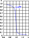
 Leave the AFS connected and connect your oscilloscope or voltmeter to the following points: negative probe to either AFS terminal #4 or engine earth, positive probe to AFS terminal #5. Turn the ignition on but don't start the engine. While warming the sensor with a hairdryer or cooling it with freezer aerosol spray the resistance (between terminals #5 and #4) and the signal output voltage (at terminal #5) should vary as shown on the diagram or described by the given formulae.
If you obtained 0 V, check that the ATS output is not shorted to the earth. Check the wiring back to the ECU. If you find no problem with the wiring and the voltage supplies and earth connections to the ECU are all right, the ECU itself is suspect. If you obtained 4.9-5.1 V, the ATS or its earth connection is open. If you found the nominal battery voltage (engine stopped: 12-13 V, cranking: 9-12 V, running: 13.8-14.8 V) instead of the specified ones, check for a short circuit to battery positive somewhere.
Coolant Temperature Sensor (CTS)
| Term. | ECU pin | |||||
|---|---|---|---|---|---|---|
| LE-J | LE-J* | MP3.1 | ML4.1 | M1.3 | G6.10 | |
| 1 | 13 | 4/5 | 6/15 | 5 | 30 | 11 |
| 2 | 10 | 8 | 13 | 13 | 45 | 24 |
| * ECU on top of AFS. | ||||||
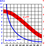 Leave the sensor connected and connect your oscilloscope or voltmeter to the following points: negative probe to either CTS terminal #1 or engine earth, positive probe to AFS terminal #2. Start with a cold engine. As the engine is started and it warms up gradually, the resistance or the signal output voltage should vary as shown on the diagram or described by the given formulae.
If you obtained 0 V, check that the CTS output is not shorted to the earth. Check the wiring back to the ECU. If you find no problem with the wiring and the voltage supplies and earth connections to the ECU are all right, the ECU itself is suspect. If you obtained 4.9-5.1 V, the CTS or its earth connection is open. If you found the nominal battery voltage (engine stopped: 12-13 V, cranking: 9-12 V, running: 13.8-14.8 V) instead of the specified ones, check for a short circuit to battery positive somewhere.
CO potentiometer (CO pot)
| Term. | ECU pin | ||
|---|---|---|---|
| MP3.1 | ML4.1 | G6.10 | |
| 1 | 24 | 30 | ? |
| 3 | 9 | 9 | ? |
| 4 | 6/15 | 6 | ? |
Check that the AFS/ATS connector is firmly connected and making good contact. Connect your oscilloscope negative probe to either AFS terminal #4 or engine earth, positive probe to terminal #1. Connect a CO exhaust content meter to the exhaust system. Set the CO to the correct level; the voltage accross the potentiometer should be between 2.4 and 2.5 V. Note the exact value then turn the CO pot in both directions to observe a smooth change of voltage between 2 and 3 V (the CO content will change between 0.8% and 1.5% accordingly). If instead of varying smoothly it is stepped, drops to zero or becomes open circuit, jumps outside the parameters specified, the potentiometer is suspect. Upon successful testing, return the potentiometer exactly to the setting noted.
If the voltage on the CO pot does not change when it is being turned, check the reference voltage of 5±1 V on terminal #3, then look for a good earth at #4 (max 0.25 V). You can test the potentiometer itself by disconnecting the AFS/ATS plug and looking for a resistance between terminals #1 and #4: as you fully turn the adjustment screw in both directions, the resistance should smoothly vary between 270 and 520 ohm.
Crank Angle Sensor (CAS)
| Term. | ECU pin | |||
|---|---|---|---|---|
| MP3.1 | ML4.1 | M1.3 | G6.10 | |
| 1 | 25 | 25 | 47 | 14 |
| 2 | 23 | 23 | 48 | 31 |
| 3 | 5 | 23 | 19 | 31 |
There are several ways to test this component depending on whether the engine can be started or not, and depending on the instruments at hand.
First of all, inspect the connectors for corrosion or other damage, check that the connectors are firmly connected and making good contact. Remove the sensor and inspect it for corrosion or other damage. Measure the resistance: between terminals #1 and #2 the resistance should be 600-1600 ohm. The CAS is connected by a shielded cable to protect it from radio frequency interferece.
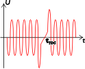
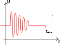
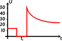
If the engine is unable to run, measurements are made by cranking the engine. Disconnect the sensor and connect an oscilloscope between terminals #1 and #2. While cranking the engine, a minimum AC voltage of 4-5 Vpp should be measured. The peaks should be even as shown on the diagram (apart from the one signaling the top dead center position): smaller or deformed individual peaks indicate missing or damaged CAS lobes on the flywheel.
 If the engine is able to run, reconnect the CAS and backprobe its terminals with the oscilloscope. Run the engine at various revolutions and check for the same waveforms.
If an oscilloscope is not available, an AC voltmeter can give approximate results: it can confirm that the CAS is working somehow but it won't indicate CAS lobe damage. Connect the voltmeter between terminals #1 and #2. While cranking the engine, minimum AC voltage of about 0.7 Vrms should be measured. Higher values (up to even 1.5 V) are also common.
On terminal #1 of the sensor the following AC voltages should be present: when cranking, 1.4 Vrms or 4.0 Vpp, when idling, 2.8 Vrms or 8.0 Vpp, when cruising, 5.0 Vrms or 14.0 Vpp. On the other terminals (#3, a screen wire, may not be fitted) a maximum of 0.25 V should be measured with the engine running. If the shield wire is present, the resistance between it and the other terminals should be infinite.
It is very likely that the engine will not start with the voltmeter connected as the current drawn by the meter changes the electrical conditions in the system. The solution is to rev the engine up to 2000 rpm, then connect the meter probes. The engine will not be harmed if the impedance of the voltmeter is above 10 Mohm and it is not erroneously connected. Otherwise, the ECU might be damaged!
Distributor & timing
On Motronic systems the distributor only serves to distribute the high tension pulses to the spark plugs. The timing is not adjustable but can be checked for satisfactory operation: at 2000 rpm the timing advance should be 30°±5°, at 3000 rpm 40°±5°.
Electronic Control Unit (ECU)
| Purpose | ECU pin | |||||
|---|---|---|---|---|---|---|
| LE-J | LE-J* | MP3.1 | ML4.1 | M1.3 | G6.10 | |
| positive feed | 4 | — | 18 | 18 | 18 | 29 |
| ground | 13 | 4/5 | 5/27 | 16/19 | 19 | 13/16/17 |
| fuel pump relay | 1 | 2 | 20 | 20 | 3 | 5 |
| injection relay | 1 | 12 | 16 | — | 36 | 21 |
| A/C compressor cutoff relay | — | — | 32 | — | — | 6 |
| fuel vapor purge valve | — | — | — | — | 5 | — |
| tachometer | 1 in | 1 in | 21 out | — | — | 3 out |
| * ECU on top of AFS. | ||||||
There is no way to directly test the ECU (unless, of course, you have a specialized diagnostic computer) but some test procedures described here can lead to the suspicion of ECU failure. Be careful, however: never try a good replacement ECU in your suspected car. If there is something wrong in the rest of the system that killed your ECU, the replacement one might get killed, too. If you have to test your ECU, go to a known good car with your computer and test it there; this way you'll risk nothing.
The ECU is much more reliable than it is often supposed to be. Certainly, it can fail as any other electronic device can but most garages are too quick to condemn it. And even if it is faulty, the cause is almost always either a bad soldering joint inside or a bad transistor in the end amplifier. Resoldering is free but even a new transistor might only cost the fraction of the price of a new unit.
Idle Speed Control Motor (ISCM)
Mono-Jetronic and Magneti Marelli
| Term. | ECU pin | |
|---|---|---|
| M-J | G6.10 | |
| 1 | 3 | ? |
| 2 | 23 | ? |
| 3 | 24 | ? |
| 4 | GND | ? |
On the Mono-Jetronic, the resistance between pins #1 and #2 of the motor should be around 5.5 ohms. The contact between pins #3 and #4 should be closed when the throttle is closed and open when the throttle is opened.
Idle Speed Control Valve (ISCV)
Motronic
| Term. | ECU pin | |
|---|---|---|
| MP3.1 | ML4.1 | |
| 1 | 29 | 33 |
| 2 | GND | 35 |
Start checking with the engine idling. Load the system by switching on the headlamps, rear screen heater and the air blower motor set to high. The idle speed should not change significantly. Squeeze one of the hoses leading to the ISCV. The idle speed should rise abruptly but return to normal in a little while.
Remove the connector and measure the resistance of the valve solenoid between its two terminals: it should be around 8 ohms. You can also try connecting the battery voltage to terminal #2 with terminal #1 earthed, the ISCV has to activate; but do this only briefly to avoid damage to the valve.
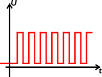 The best way to check the functioning of the valve is by using an oscilloscope. Leave its plug connected, connect your instrument between terminal #1 and the earth. With the engine running, you should see a stable square waveform. The frequency is around 100-110 Hz but the duty cycle (the percentage of the individual pulses to the total) will vary according to engine load. In a cold engine, you should see about 56-58%, in a hot engine without load 40-44%, this will rise to 44-50 under load. The minimum duty cycle is 25%, the maximum 75%. The minimum value of the pulses should be 0.3 V at most while the highest value should reach the nominal board voltage.
Load the system again by switching on the headlamps, rear screen heater and blower motor. The duty cycle will increase but the frequency should remain constant. An air leak causes the ISCV to pulse less than normal.
If the resistance test showed the valve to be perfect but you can find no signal on its terminal, check its wiring back to the computer.
Ignition coil & module
Check that the coil terminals are firmly connected and making good contact. Clean any accumulated dirt and residue. Inspect the coils for signs of tracking.
 Connect an oscilloscope or a dwell meter to either terminal #1 or #2 (they are connected together internally). If the engine cannot run, crank it and observe the waveform. The primary voltage peaks should reach a minimum of 200 V. Less than that may indicate defetive primary windings.
If the waveform is not satisfactory, check the CAS first, then, with the ingnition on, check for nominal 12-13 V at the positive terminals (#3 or #4). Then repeat the same for negative terminals #1 or #2. If you found no voltage at the negative end, remove the wire and measure again. If still no voltage, check the coil primary resistance (0.8 ohms between terminals #2 and #3). But if you had voltage once you removed the wire, check for a short to earth between the coil and the ignition module. If none found, the module itself is suspect.
| Term. | ECU pin | ||||
|---|---|---|---|---|---|
| LE-J | MP3.1 | ML4.1 | M1.3 | G6.10 | |
| 1 | 1 | — | — | — | — |
| 2 | — | 1 | — | — | — |
| 5 | — | — | 1 | 1 | 1* |
| 6 | — | — | 1 | 1 | 19* |
| 7 | — | 2 | — | — | — |
| * Coil driven directly. | |||||
Otherwise, go on to the ignition module. You should get 12-13 V on terminals #4 and #1, and a good earth (max 0.25 V) on #2. Crank the engine and observe the square waveform or duty cycle at the module terminals #5 and #6 and back at the ECU. If no waveform can be detected, check the wiring back to the ECU and its connections. If the ECU does not send the signal. it is suspect. If it does but the module gives no output, it is faulty.
If the engine runs, observe the waveform at coil terminal #1. The duty cycle will rise with elevating engine speed: 15-30% while cranking, 10-20 at 1000 rpm, 25-35 at 2000 rpm, 30-40 at 3000 rpm and 40-50 at 4000 rpm. In contrast, the pulse length remains rather stable: while 15-20 ms while cranking, around 6 ms throughout the whole rpm range. At the same time, check the primary voltage peak level (min 200 V) and the dynamic voltage drop (max 2.5 V). To accomplish this second one, first check the earth of the ignition module, and be sure that no radio suppressor or theft alarm circuits are connected to the coil negative terminal. If these checks turn out OK yet the primary peak voltage and the dwell percent values are too high, the ignition amplifier is definitely faulty.
![]() Don't forget that you are working in the vicinity of the HT parts where dangerously high voltages can be found. Avoid any measurement or contact with the secondary side of the coil, HT leads and spark plugs!
Don't forget that you are working in the vicinity of the HT parts where dangerously high voltages can be found. Avoid any measurement or contact with the secondary side of the coil, HT leads and spark plugs!
Ignition HT
![]() The voltage in the ignition secondary system can reach as much as 20,000 V—a shock can be not only nasty but might keep you from driving a Citroën ever again... We will only describe those tests which can be carried out without danger. The rest can be measured as well with appropriate equipment and practice but you have to let a specialist do this.
The voltage in the ignition secondary system can reach as much as 20,000 V—a shock can be not only nasty but might keep you from driving a Citroën ever again... We will only describe those tests which can be carried out without danger. The rest can be measured as well with appropriate equipment and practice but you have to let a specialist do this.
Thus, the following tests are done with the ignition off. The coil tower should be checked for tracking (skeletal etched on the tower might indicate this). Clean and polish the tower if necessary. Remove the HT leads, look for any damage, poor insulation. Measure the resistance and if it exceeds 20 kohm, replace the lead. Renew leads that are excessively oily or dirty. You should never use unsuppressed or copper wire HT leads because they usually destroy the ECU.
Inspect the distributor cap for scratches, cracks, tracking, oil or moisture. Oil can enter through a defective distributor base seal, water through a failing head gasket. Clean the cap thoroughly.
If the engine cannot run, you should check for sparks. A safe way to accomplish this is to use a spark jumper between the HT lead and the cylinder head. If you found no spark, repeat the check by connecting the jumper between the main coil HT lead and the cylinder head. If you find spark here, the HT leads, the distributor and the spark plugs themselves should be checked. If no spark can be observed, go back to check the primary side. If the primary is switching yet there is no spark, the coil is faulty, but before renewing it check the main lead and its contact to the coil tower. The resistance between the coil tower and each primary coil terminal in turn should be 6500 ohm.
Injectors
| Term. | ECU pin | |||||
|---|---|---|---|---|---|---|
| LE-J | LE-J* | MP3.1 | ML4.1 | M1.3 | G6.10 | |
| 1 | 12 | 3 | 14 | 14 | 16+17 | 18 |
| 2 | 9 | 4/5 | 35 | 35 | 37 | — |
| * ECU on top of AFS. | ||||||
In the case of a Motronic engine management system, you can check the basic operation of the injectors.
 Connect your oscilloscope or dwell meter to the following points: negative probe to engine earth, positive probe to any injector's terminal #1.
If the engine is unable to run, crank it and observe the waveform or the duty cycle. The duty cycle in a cold engine is 11-12 ms, in a warm engine 4-4.5 ms.
If you find no readout, reconnect the probe to the other terminal. If no signal is present or it is not similar in shape to the required, then first check the CAS and for a supply voltage at terminal #2 corresponding to the nominal battery voltage (engine stopped: 12-13 V, cranking: 9-12 V, running: 13.8-14.8 V). If no voltage is found, check the injector resistance: remove the plug and measure between the terminals, you should get 15-17 ohm. Then disconnect the fuel injection relay and measure the resistance between the corresponding ECU pins where you should see 4 ohm.
If still no luck, first check the situation with the other injectors as well. If nothing was found, switch off the ignition, disconnect the ECU, switch the iginition on again and jumper the ECU pin corresponding to the injector terminal #1 to earth using a jumper lead, but only for a very short time! If the injector actuates now and the ECU voltage supplies and earths are in good condition, the ECU itself is suspect. If the injector does not actuate, either its wiring or the injector itself is suspect. Check the wiring with a resistance meter.
If the engine runs, record the values obtained from the oscilloscope or dwell meter at idle speed, 2000 rpm, 3000 rpm, during slow and rapid throttle increase, and deceleration (rev then engine up to 3000 rpm and release the throttle suddenly). The duty cycle of a cold engine is about 3-3.5 ms, while in a warm one 2-2.5 ms. The percentage value or the pulse width should increase as the engine revolution is raised but the millisecond value should not raise significantly if the acceleration is slow. Under snap acceleration, however, it should raise up to 6 ms. Under deceleration in a warm engine the pulse width should immediately drop to zero and reappear when the revolution drops below 1200 rpm. It if fails to do so, check the throttle butterfly, the TS or TPS. If the injectors pulse with the wrong timing, check the CTS and the AFS.
You can check the quantity of fuel delivered by the injector by removing one and orienting it to inject the fuel into a vessel with graduated scale. Let the engine idle for 60 seconds and measure the quantity of fuel delivered. Different injectors have a different delivery capacity:
| Bosch part number | Fuel quantity |
|---|---|
| 0 280 150 114 | 185 ccm/minute |
| 0 280 150 116 | 185 ccm/minute |
| 0 280 150 121 | 178 ccm/minute |
| 0 280 150 125 | 188 ccm/minute |
| 0 280 150 201 | 236 ccm/minute |
| 0 280 150 203 | 185 ccm/minute |
| 0 280 150 208 | 133 ccm/minute |
| 0 280 150 209 | 176 ccm/minute |
| 0 280 150 211 | 146 ccm/minute |
| 0 280 150 614 | 189 ccm/minute |
| 0 280 150 704 | 170 ccm/minute |
| 0 280 150 715 | 149 ccm/minute |
| 0 280 150 716 | 134 ccm/minute |
Manifold Absolute Pressure Sensor (MAP)
Motronic and Magneti Marelli
| Term. | ECU pin | |
|---|---|---|
| MP3.1 | G6.10 | |
| 1 | ? | 27? |
| 2 | ? | 9? |
| 3 | ? | 12? |
On Motronic MP3.1 systems, remove the vacuum hose from the inlet manifold, and attach a manual vacuum pump. Create a vacuum of about 750 mbar (if the vacuum pressure drops, there is a leak somewhere). Re-attach the pump directly to the MAP sensor and repeat the test. If the vacuum drops again, the sensor should be replaced.
Oxygen Sensor (OS)
| Term. | ECU pin | ||
|---|---|---|---|
| LE-J | M1.3 | G6.10 | |
| Heat 1 | +ve | +ve | +ve |
| Heat 2 | 13 | 14/24 | GND |
| Signal | 20 | 28 | 30 |
| Shield | 5 | 10 | 12 |
This component (also called lambda sensor) is located in the exhaust pipe before the catalytic converter. Access is possible only from beneath, using an inspection pit or supporting the car on safety stands. Check that its connector is firmly connected and making good contact.
Before testing the sensor, check the other parts of the system and measure the CO extent of the exhaust gas. Otherwise you might be fooled to think that the sensor is suspect and replace it unnecessarily, while it does nothing else but tries to cure the symptoms of another failure in the injection system.
Warm the engine to the operating temperature (the cooling fan cuts in and out). Stop the engine, turn off the ignition. Locate the wiring at the right hand corner of the engine compartment, going down between the engine and the right suspension sphere. Disconnect the two connectors (one is black, the other is blue). Connect your oscilloscope or voltmeter to the following points: negative probe to engine earth, positive probe to one of the pins in the blue connector. Note the measured value. Turn on the ignition (do not start the engine yet) and check the meter again: the readout should change.
![]() You should not apply external voltage to the sensor (hence, avoid resistance measuring to be on the safe side) but measuring its output can cause no harm.
You should not apply external voltage to the sensor (hence, avoid resistance measuring to be on the safe side) but measuring its output can cause no harm.
 Make sure that your meter and probe leads are not in the way of any belt or other moving part, then start the engine. Run the engine at high idle for one or two minutes to warm up the sensor completely. The sensor generates voltage somewhere between 0 and 1 V according to the lambda value (lambda=1 means about 0.45 V). If the sensor is good, you will see swift transitions between high (about 0.7 V) and low (about 0.2 V) voltages. Because of the rapid changes a simple digital multimeter is not of much help here, you'll either need one with a bargraph display, an analog meter or an oscilloscope.
If you have a steady readout of about 0.45 V, don't panic, it might not be hot yet. Rev the engine above 2000 rpm for a while then check again.
If it stays steady, try to reconnect the voltmeter leads to the sensor itself rather than the connector in the engine compartment and repeat the above. If nothing changes, either the sensor is bad or it is carbon fouled (especially if the car has been running rich lately, check a spark plug to see if it is fouled, too). Also, the sensor is constantly comparing the exhaust gas oxygen content to that of the outside world. If the outside of the sensor is coated with oil or road dirt, it cannot give you any correct output.
If the sensor is suspected to give false input to the ECU, causing inadequate mixture, uneven or fluctuating idle speed, you can confirm your suspicion by disconnecting the sensor at the connector behind the engine. A well adjusted injection system should run quite well even without the sensor connected, with a lambda value not deviating too much from 1. Don't use the car with the sensor disconnected as the richer mixture could harm the catalytic converter but a short check will not damage anything.
The oxygen sensor is very sensitive. You should not drop or knock it, never use any cleaning solvent on it. Silicone based sealants (more precisely the acid fumes they emit while curing) are one of the biggest enemies of the sensors, hence never use such products around the engine (rocker cover, oil pan, air intake hoses) unless the label specifically states "oxygen sensor safe". Lead, the number one poison to catalytic converters will ruin the oxygen sensor as well.
If the tests above show that the sensor does fail, you have not much to lose: try to clean the outside of the sensor from oily grime that might be present, without cleaners, only with a damp lint-free cloth. If the inside of the sensor is carbon fouled, you may try to leave the sensor disconnected, run the engine at about 2000 rpm for one or two minutes and create a vacuum leak big enough for the engine to slow down but not to stall. If you are lucky, the extra heat generated will clean off the sensor.
Self Diagnosis Plug (SD)
| Term. | ECU pin | |||||
|---|---|---|---|---|---|---|
| LE-J | LE-J* | MP3.1 | ML4.1 | M1.3 | G6.10 | |
| 1 | 22 | — | 12 | 12 | 55 | 28 |
| 2 | — | — | 4 | 4 | 15 | 4 |
| Lamp | — | — | 17 | 17 | 13 | 22 |
| * ECU on top of AFS. | ||||||
On Jetronic systems this connector cannot be used to read error codes, only to check some ignition settings.
Turn off the ignition and check that the dashboard warning lamp remains off. Then switch the ignition on and check that the lamp comes on. Start the engine and allow it to idle, check that the lamp goes out. If the lamp comes on during the normal engine operation, check the error codes stored in the ECU.
With the ignition still on, remove the connector of the CTS. Start the engine and let it idle. The warning lamp should come and stay on. Stop the engine and turn the ignition on again, the warning lamp should still remain on. Reconnect the CTS. Start the engine idling, the warning lamp should go out. Disconnecting minor sensors will not cause the warning lamp to remain on but will be recorded in the ECU. Clear the ECU of the error codes you have just made it record.
If the warning lamp misbehaves or you have problems reading and clearing the ECU error codes, connect your oscilloscope or voltmeter to the following points: negative probe to engine earth, positive probe to SD terminal #2. The readout should be the nominal battery voltage (engine stopped: 12-13 V, cranking: 9-12 V, running: 13.8-14.8 V). Backprobe the ECU terminal #17??? where you should find the same nominal battery voltage. If you don't have this second, check the warning lamp bulb and the wiring to it.
With the ignition on, remove the connector of the CTS. Start the engine and leave it to idle. The warning lamp should come one, and the ECU #17 voltage should drop to zero. Without ignition, check the wiring between ECU #17 and SD #1, then between ECU #17 and SD #2 ??? by looking for zero resistance.
Clear the ECU of the error codes you have just made it record.
Throttle Potentiometer (TP)
Mono-Jetronic and Magneti Marelli
| Term. | ECU pin | ||
|---|---|---|---|
| M-J | MP3.1 | G6.10 | |
| 1 | 7 | 15 | 7 |
| 2 | 8 | 9 | 25 |
| 3 | 18 | 3 | 11 |
| 4 | GND | — | — |
The Bosch Mono-Jetronic system uses a potentiometer to check the actual position of the throttle pedal. Between pins #1 and #5 you should find a constant reference voltage of 4.5 to 5.5 V. The voltage will gradually increase from 1.0 V to 4.5 V between pins #1 and #2, and from 0 V to 4 V between pins #1 and #4 as the throttle is opened.
The testing procedure is quite similar on the Motronic MP3.1 as well. The value to look for is a voltage varying between 0.6 V and 4 V on pins #1 and #3 as the throttle is opened.
Throttle Switch (TS)
Jetronic and Motronic
| Term. | ECU pin | |||
|---|---|---|---|---|
| LE-J | LE-J* | ML4.1 | M1.3 | |
| 2 | 2 | 15 | 2 | 52 |
| 3 | 3 | 14 | 3 | 53 |
| 18 | 9 | 4/5 | 5 | 30 |
| * ECU on top of AFS. | ||||
On Jetronic systems, disconnect the connector of the switch and connect your oscilloscope or voltmeter to the following points: negative probe to engine earth, positive probe to TS terminal #2. You should read at least 9 V while cranking the engine with the starter. If this is not present, check the wiring.
On On Motronic ML4.1 systems, leave the TS connected and connect your oscilloscope or voltmeter to the following points: negative probe to either TS terminal #18 or engine earth, positive probe to #2. The meter should indicate 0 V. If it shows more (5 V), loosen the retaining screws and adjust the position of the switch so that 0 V is obtained. If the zero does not want to appear, check the position of the throttle butterfly, check the earth wiring of the TS and measure its resistance as follows.
If you had 0 V in the first test, open the throttle. The voltage measured should rise to 5 V. If it is lower or zero, check that there is no short circuit between TS terminal #2 and the earth. Then disconnect the connector and look for 5 V at terminal #2. If you can't find this 5 V, check the wiring back to the ECU.
If the voltage rose to 5 V as you opened the throttle, reconnect the meter to TS terminal #3. With the throttle either in idle position or just open, you should read 5 V. If you can't see this, check the earth connection and that this terminal is not shorted to the earth somehow. Disconnect the connector and look for 5 V at terminal #3. If you can find nothing, check the wiring back to the ECU.
As you open the throttle, from 72° the voltage output should drop to 0 V. If it doesn't, the TS is suspect.
On On Motronic MP3.1 systems, leave the TS connected and check for 0.6 V between terminals 1 and 3 (ignition on). When you depress the throttle fully, the voltage should rise to 4 V. If the 0.6 V was not present, look for 5 V now. If not found, check the 5 V at the ECU terminal #9.
Then, on all systems except MP3.1, disconnect the TS, connect an ohmmeter between TS terminals #18 and #2. As the throttle is closed, the resistance should be practically 0 ohm. Open the throttle slowly. The TS should break the contact with a noticable click and become open (infinite resistance), remaining so even when the throttle is fully opened. Then reconnect the ohmmeter between terminals #18 and #3. As the throttle is closed again, the resistance should be infinite. Open the throttle again; as soon as you reach 72°, the resistance should drop to zero. If the TS does not behave as described, it is broken.
EMS error codes
When the EMS warning light (symbolizing a transistor, similar to a letter K) lights up on the instrument panel, don't wait too long. Unless the failure is permanent, after twenty engine starts the fault flag will be automatically cleared. Not all errors that store an error code in the computer will light up the warning light, less serious and passing errors do not.
The fault codes are easily retrieved by a Fault Code Reader, a special diagnostic equipment. At least they are supposed to be special but it is very easy to rig such an equipment. First of all, many systems only need a single switch to operate the diagnostic readout, the codes will be displayed using the mentioned warning light on the dashboard. Some other systems will use a LED in the diagnostic equipment itself (you might prefer this solution even if your system can use the dashboard lamp as this spares you the trouble of finding a long wire so that you can sit back behind the steering wheel to see the lamp). The circuit diagram shows how utterly simple such a "specialized diagnostic equipment" looks like.
Once you have the reader connected to the green Self Diagnosis plug and the ground, switch on the ignition. Close the switch for three seconds (the LED or the dashboard lamp should stay off), then open it. The LED will flash n times, then pause for 1.5 seconds, then flash m times. The code the system tries to tell you is 10n+m. Wait three seconds before you repeat the procedure.
The first code you receive will be 12, meaning Test Start. The last one will be 11, Test End. If there are no other codes between these two, the ECU has nothing to say. Otherwise, check the meaning of the codes in the following table (not all code numbers can appear on all systems):
|
|
After you obtained the Test End code, you can repeat the whole procedure from the beginning.
Note that the computer cannot actually check the sensors themselves, only the input it is fed with. An error code means that there is (was) some malfunction in the circuit mentioned but that can be (and most of the time it is) caused by an error in the wiring between the sensor and the ECU, or a bad contact in the several connectors between the two end points. Thus, start with checking the wiring and only then the sensor itself.
If you just peeked at the codes to see what to tell the workshop, don't clear the codes so that they will also have a chance to see them. However, if you did correct the fault yourself, reset the fault codes by performing the previous reading test until you receive the code 11, then close the switch for more than ten seconds. The warning lamp should stay off.
On some systems, the injectors and the idle speed control valve can also be checked using the unit: close the switch, turn on the ignition (without starting the engine), and wait for three seconds. You can observe the injectors functioning by their vibration and clicking. Open the switch quickly to avoid any greater quantity of excess fuel to enter the engine. If you repeat the test by closing the accessory switch once more for three seconds, the ISCV will operate shortly this time.
EFI troubleshooting
![]() First of all, a few very important precautions: never start the engine without the battery cables firmly connected; never jump the battery to start the car; never remove the battery cables with the engine running; never charge the battery with the cables connected; never disconnect or reconnect the ECU connector with the ignition on. When using a voltmeter to test the various components always make sure that the impedance of the meter exceeds 10 Mohm, otherwise the ECU might be damaged!
First of all, a few very important precautions: never start the engine without the battery cables firmly connected; never jump the battery to start the car; never remove the battery cables with the engine running; never charge the battery with the cables connected; never disconnect or reconnect the ECU connector with the ignition on. When using a voltmeter to test the various components always make sure that the impedance of the meter exceeds 10 Mohm, otherwise the ECU might be damaged!
Before you delve into the sometimes complicated details of the fuel injection system, check that the ignition system (battery voltage, distributor, spark plugs, ignition coil and timing) and the engine itself (compression, adjustment of valves, engine oil pressure) are in proper condition.
If you have a later, Motronic engine management system that is capable of storing an error code whenever it detects a malfunction, start by reading these codes out.
The engine does not start although the starter motor operates.
- Check that all hose lines are securely attached and firmly tightened, that the hoses themselves are in good condition, not cracked, kinked or damaged.
- Check to see whether the fuel pump operates (it is located above the right rear wheel, its operation can be heard as a buzzing sound if you listen to it while an assistant is cranking the engine), check whether voltage is present at its connector while the engine is being cranked. If the voltage is present but the pump is not working, it has to be replaced. If you found no voltage, the fuse and the relay feeding the fuel pump might be suspect. Check and replace them if necessary.
- If the pump does supply fuel, test the pressure in the system. Check the fuel lines and filters as well as the pressure regulator.
- Check the CTS. If it is open or became disconnected, the engine will not start.
- Jetronic only: If you found the fuel pressure sufficient, check the auxiliary air valve. If it is faulty, replace it. Motronic only: Check the crank angle sensor.
- Check the whole air intake system (the manifold and every component and hose attached) for vacuum leaks. You can localize the leaks present by using compressed air and soapy water.
- A shortened injector can also cause the engine to refuse to start. Disconnect the injectors one by one until you find the faulty one or check them by measuring their resistance.
- Finally, test the AFS. If it became completely faulty or disconnected, the engine will not start.
The engine starts but it dies in a short while.
- Test the fuel pressure in the system. If it is sufficient but drops after the end of the starting process, listen to the operation of the fuel pump. If the pump keeps functioning, the pressure regulator is faulty.
- Jetronic only: If you found the fuel pressure sufficient, check the auxiliary air valve. If it is faulty, replace it.
- Finally, test the AFS.
The engine has cold starting problems.
- Check the CTS.
- Jetronic only: Check the auxiliary air valve. If it is faulty, replace it.
The engine does not accept fuel smoothly.
- Test the throttle switch and adjust it if necessary.
- Check the whole air intake system (the manifold and every component and hose attached) for vacuum leaks. You can localize the leaks present by using compressed air and soapy water.
- Jetronic only: Check the auxiliary air valve. If it is faulty, replace it.
- Finally, test the AFS.
- If you successfully found and repaired the failure, don't forget to measure and correct the idle speed and the concentration of CO again.
The engine runs but it misses every now and then.
- Engine misses can be caused by bad contacts of the ECU connector. With the ignition switched off, disconnect, clean and reconnect the connector. Check the earth terminals for continuity and good contacts. Similarly, check the wiring to the fuel injector relay.
- Check the quantity of fuel delivered by the injectors.
- If nothing has cured the problem so far, test the AFS. If the missing spot appears always at the same engine speed (rpm), the cause will probably be a worn AFS track. You can bend the wiper arm carefully so that it touches the track at a slightly different radius.
- If the AFS is OK, the ECU itself might be at fault.
Fuel consumption is too high.
- Test the fuel pressure in the system. If it is sufficient, check the quantity of fuel delivered by the injectors.
- If the consumption is OK on the highway but too high in town, driving short trips, check the functioning of the cold start systems (auxiliary air valve).
- Finally, test the AFS and examine the idle speed and mixture settings.
The engine does not reach its maximum power.
- Check whether the throttle butterfly is closed. Try to push it farther and observe the engine speed in the meantime. If the speed decreases, reset the adjusting screw.
- Test the fuel pressure in the system. If it is sufficient, Check the whole air intake system (the manifold and every component and hose attached) for vacuum leaks. You can localize the leaks present by using compressed air and soapy water.
- Check that the air filter is clean and the fuel filter is not clogged.
- Finally, test the AFS.
Idle speed problems
Probably the nastiest problems with fuel injection and integrated engine management systems are those of the idle speed. During normal driving the circumstances in the engine are average, dictated mainly by the AFS or MAP sensor (roughly speaking, the position of the throttle pedal), meaning that many other sensor or mechanical errors in the system could go practically unnoticed. On the other hand, the idle speed relies mainly (or in some systems, totally) on the electronic control unit, causing sometimes even the slightest disturbances in the system to be manifested in uneven idle speed.
The first component to check is the throttle switch which informs that ECU about the position of the throttle pedal. If it is out of adjustment or even malfunctioning, the ECU has no way of knowing that it is supposed to work in idle speed mode. Before you start with the actual testing, try to push the throttle butterfly a little bit farther. If the idle speed changes, the switch probably needs readjustment.
To go on, you would need an exhaust gas analyser. Before you start to spend your time chasing faulty components, it is good to be sure that it's not a simple misadjustment that's causing the trouble. You can probably find a garage nearby where they can measure this for you. As a preliminary test, take a look at the spark plugs. Carbon fouling, for instance, means an over-rich mixture.
So, if you cannot set it to the required values of idle speed and CO content, or the idle is still uneven, check the whole air intake system (the manifold and every component and hose attached) for vacuum leaks. You can localize the leaks present by using compressed air and soapy water.
If the engine revolution drops way below idle for a while when you release the throttle pedal suddenly, then climbs back and stays normal (although a cold engine might not come back to normal idle but cut off when the revolution drops that low), you must have a vacuum leak past the airflow meter. During deceleration (throttle closed, engine running) the high vacuum sucks some additional air into the engine through that leak. As this is already past the airflow meter, this additional air is not measured and accounted for by the injection computer. The surplus makes the fuel-air mixture leaner by a considerable amount, starving the engine. However, as the revolution drops, the vacuum weakens, the additional air intake is reduced and the situation normalizes: this is why the engine returns to normal idling after a few moments.
Check the rubber hose carefully between the meter and the throttle butterfly housing for cracks and holes. The crack can be very small and hardly visible, yet cause problems as the vacuum is quite high; the sucking effect opens even a small crack quite wide. Note that two smaller hoses detach from the big hose, one going to the auxiliary air valve beneath the distributor (access is difficult because of the battery, you might want to remove the latter), the second to the engine oil filler cap. Those hoses (and the points where they connect) are suspect, too.
If the crack it not visible immediately, use carburettor cleaner spay. Spray a mist over the suspected part of the hose. If there is a crack, the engine will suck air and the cleaner through it. As the cleaner acts like fuel for the engine, it will speed up for a moment. When you spotted the trouble area, remove the hose and check visually, bending and twisting it until you reveal the crack. You could also remove the suspected hoses, plugging one end and letting compressed air into it. Soapy water will bubble where air escapes.
If you do find a leak, you have to close it. Glue is hardly an option because these hoses are made from hard rubber and are subject to permanent heat and vibration (although you could try using some silicone sealant, after having cleaned the surfaces very carefully. Be sure to use sealant for automotive use, stating 'oxygen sensor safe' if you have a catalytic converter, not bathroom silicone). With the smaller hoses you could use a coolant hose repair kit (a rubber band bandage, eg. from Holts).
If it wasn't an air leak, you have to go back testing. It is important to know whether the idle speed is constantly changing, fluctuating, or just too high or too low. It is also vital to know whether there is any relation between the idle speed problems and the temperature of the engine. If the problems appear only in cold or warm engine, the coolant temperature sensor and the auxiliary air valve should be checked.
On Motronic and Magneti Marelli systems the idle speed is constantly adjusted by the ECU. The Motronic uses an idle speed control valve that opens and closes several times in a second to increase or decrease the current idle speed, while the Magneti Marelli system can adjust it even more smoothly with an idle control stepper motor which not only opens or closes but can fine adjust the amount of air passing through the idle bypass around the throttle butterfly.
The Magneti Marelli stepper motor is situated on the top left of the engine. Pull out the metal cylinder (it's only held by two rubber O-rings), remove the nut and take out the copper cylinder. Clean both cylinder and the housing. Remove the dirt from the four small holes in the top of the cylinder piercing them very carefully with a thin wire. Refit the inner parts completely into the housing and put them back into the cylinder.
Check whether the injectors are in good mechanical condition: with the engine running, detach one injector plug after the other. If the injector is good, the engine speed must drop as its plug is disconnected.
A faulty oxygen sensor can also make the idle speed change or fluctuate up and down constantly.
Test the fuel pressure in the system. If it is sufficient, go on to testing the AFS.
If you successfully found and repaired the failure, don't forget to measure and correct the idle speed and the concentration of CO again.
Irregular idle speed in 16 TGI (Magneti Marelli engine managament system). Revolution rises periodically: Check if the air filter cap closes over the filter edge nicely. Check the hot air hose to the filter for cracks, especially on the exhaust mounting.
Frans Tak
Other failures and problems
The car runs nice for some period (might be a few kilometers or several hours) but then it starts to miss suddenly and finally stops completely. After having rested for some time (a few hours, maybe overnight) everything starts all over again.
- When the symptoms are present, go to the end of the car, to the right rear wheel. Listen for the humming noise of the fuel pump. If the pitch of the sound changes periodically, the fuel pump is struggling to supply the fuel pressure needed for the injection system. If you have the necessary equipment, measure the fuel pressure just before the injector fuel rail. If it is all right for a while then it starts to drop, and finally the engine stops, the fuel pump is obviously faulty.
- If you live in a country where the petrol you can buy is not so clean, change the fuel filter more frequently than specified (especially on BX 19 models where the factory specifies 80,000 km). Considering the low cost of the filter, it is much more reasonable to change it twice or three times as often. If you have to renew the fuel pump, renew the filter as well.
If my engine happens to stop for some reason, I can't restart it immediately. However, if I wait 10-20 minutes, it will start again.
- These are the classic symptoms of dirty injectors. There are injector cleaning fuel additives available from different manufacturers, however, they cannot be always recommended heartily. Some might harm the catalytic converter (although all of them will most certainly say on the label that they are absolutely harmless). Injection specialist workshops generally offer a reliable cleaning service, however, it is much more expensive than a bottle at the gas station.