Stroboscopic timing light
Traditionally, stroboscopes were built with xenon flashlights such as those used in photographic flashguns. However, these flashlights require a 400-600 V voltage and even more for igniting them. Needless to say, electric shocks of such voltages are often lethal. Unless you have experience in building such high voltage circuits (including proper insulation) and also have measuring equipment to help with the process, you shouldn't even think of building one.
Fortunately, with the advances of contemporary semiconductor technology, there is no need for those flashlights. There are very high intensity LED diodes available which are perfectly suited for this task. These mostly AlInGaP (Aluminum-Indium-Gallium Phosphate) LEDs come with an intensity level in the range of 10,000 to 25,000 microcandelas, which is an awful lot compared to the 5-50 mcd value of common LEDs. If you even put it into a socket with a reflector and a focusing lens, its light will be so bright that—although it's not a laser diode—you should never look directly into the light rays. Such LEDs are about ten times more expensive than regular ones but in absolute figures that's not so terrible at all: around 3-5 EUR each.
The stroboscope circuit is also much simpler than the traditional one where a DC-DC converter was needed to generate the high voltage from the 12 V DC available. This converter used high voltage capacitors, diodes and a transformer. We can spare all these components as our circuit will be perfectly happy to use the 12 V it receives from the car's battery.
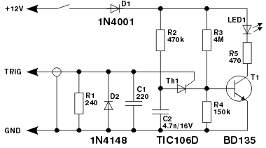
The functioning of the circuit is quite simple. The +12 V and ground wires should be clipped to the battery terminals (the D1 diode protects the circuit from accidental reverse polarity). The trigger input must not be connected directly to the ignition system in any way, use an alligator clip clipped around the insulation of the first cylinder (closest to the distributor) spark plug HT lead. Using a shielded cable for the trigger input line is essential to avoid false input from the other cylinders.
As soon as you switch the circuit on, the C2 capacitor starts to charge with the current flowing through the R2 resistor but nothing else happens as the Th1 thyristor is initially closed. When the engine is running, the trigger input collects this signal via a capacitive coupling. The first pulse opens the thyristor and the C2 capacitor discharges through the R4 resistor. The T1 transistor senses the voltage dropped on this resistor and opens, switching the LED to the +12 V supply (through a customary current limiting R5 resistor; you might need to alter its value according to the current of the LED you actually use). As soon as the C2 capacitor is fully discharged, the T1 transistor closes again and the LED goes out. The Th1 thyristor doesn't remain open because the resistance in its anode circuit is quite high, meaning that the current flowing through the thyristor is way below its holding current. Finally, everything starts again from the beginning.
The components R1, D2, C1 protect the thyristor.
Where to aim with it?
Start from the left hand side of the engine head and go down at the side of the engine, past distributor, thermostat and whatever there is, down and slightly to the front, until you reach down to the crankcase. You'll be stopped there by the clutch which is bolted on to this side of the engine. Just where the clutch connects to the engine, somewhere between the two top bolts holding the clutch in place, you'll find a longitudinal aperture that lets you look into the crankcase, to see the outer top edge of the flywheel. The aperture had a small cover plate originally, you might need to remove this. The rotating marks are on the flywheel, the stationery ones on the edge of the aperture. Clean the area and, if the marks are not visible, reinforce them with a little bit of white paint (the best paint for this is the correcting fluid used when typewriters were still topical, but a small amount of white car paint stamped there using a baby-care swab or a very fine brush is also excellent).
Just to be complete, here is the circuit diagram of a traditional flashlight stroboscope:
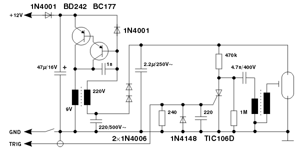
When buying the components, note that two capacitors are rated for AC voltage. The transformer in the DC-DC converter can be a simple 220 V to 9 V mains transformer for PCB-mounting, 1.5 VA is sufficient (from Schaffer or other manufacturer). The 9 V coil will be used as the primary coil. If you want to make it yourself, the primary coil has 100 turns, the secondary 2540 turns. The autotransformer driving the flashlight is a standard flashlight ignition transfomer, you can buy these at electronics stores.
We intentionally don't present a printed circuit board for this second stroboscope. First, the best solution would be to find an old flashgun and put the new circuit into its housing, retaining some components (flashlight, autotransformer, in-out switch). In this case the PCB should be designed to fit the available room. Second, we stress again that such high voltage equipment should be built only by those who have the necessary knowledge and experience; those people will find designing a PCB from scratch an easy task.