Retrofitting a coolant temperature gauge
This is rather easy on the Series II models (but read on, we have some ideas for Series I, too). The modification has been done on various models already: 15 TGE, 19 TRI, 19 TRS, 17 TZD turbo, 19 RD, 19 TZD. As far as I know, the exact same procedure should apply to all BX 15/16s (but it would be nice if someone could try and inform me about the results). Part of the modification might work on a BX 14, too (temperature meter but no warning lamp).
The BX 16/19 has two coolant temperature switches screwed into the back of the thermostat housing. The thermostat is located on the left of the engine, beneath the distributor. The switch with the blue connector actuates the yellow pre-warning lamp at about 105 °C, the yellow connector the red warning lamp at 112 °C. In contrast to this, the GTi has a switch for the red warning lamp and a sensor for the meter itself. The switch is identical, however, the sensor is different.
What you need
The modification entails replacing the blue connector switch (105 °C) of the 16/19 with the temperature sensor of the GTi, and the instrument panel of the 16/19 with that of the GTi. The original wiring of the switch will serve the sensor without additional modification. Hence, these are the two parts you have to acquire somehow.
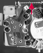
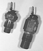 The sensor is a simple NTC resistor, without mechanical parts. Hence, it is reasonably safe to get one from a salvage yard. Take care not to buy the switch but the sensor. The sensor is 4 cm long, measured from the sensing end to the tip of the connector [left], the switch is 5.5 cm, with a longer protruding end [right]. The switch has the actuating temperature (105 or 112 °C) stamped on the side, the sensor has not. If you need the switch, too, for some reason, it would be much more reliable to purchase a new one: temperature switches tend to deteriorate over time, their operating temperature starts to shift and later the switch fails altogether.
Look for a donor car without air conditioning as those have different, double function temperature switches with two connectors. It is not a problem if you have aircon yourself, you can use the other hole in the thermostat housing—originally plugged with a screw—to install the new sensor. There will be one difference, though: the wires of this double function switch do not go straight to the dashboard as in cars without AC but are connected to a relay unit. Therefore, you cannot simply use these wires already in place (cutting them would stop the AC), you have to put a new wire between your new sensor and the instrument panel gauge yourself.
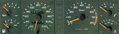
And if you did find a GTi in the salvage yard, don't leave its instrument panel alone (the one on the picture comes from a Peugeot GTi; although its design is slightly different, it is fully compatible with the BX panels). If the yard people are friendly enough you might be able to test it to see if it works OK (either in the GTi, if it is still intact to this extent) or in your own car. With some previous experience, you can dismantle your dashboard on the spot in less than ten minutes (you can drive up with the screws already removed), fit the GTi panel and see if everything works all right. Some blown light bulbs are not a catastrophe, minor scratches or discolorations can also easily be repaired, as you will have two instrument panels to combine into one. However, the meters (speedo, tacho and the four corners) should work. You might be able to swap some of them between your original and new instrument panels, however, this might require major dismantling of the unit, so it's not for the fainthearted. But if you want to have your original tachometer back with your original redline zone, you have to take this route. It is advisable to do so because, if the redlining is incorrect, some nitwit at a garage might not pay attention and torture the engine into too high a revolution during some tests or repairs. Some parts (eg. the delay module of the oil level/oil pressure meter in the upper left corner) even differ in the electronic panel, so swapping is not an option there.
In a diesel you'll have to combine your two panels into one, anyway, as the tachometer is not compatible. Don't forget to remove the bulb of the yellow warning light, leaving it there would upset the meter.
For a few days Jens and I thought about sparing the GTi panel and using the oil pressure meter which is idle after the initial delay period when it shows the oil level. However, this meter is so idle that it doesn't have the necessary circuits and connections in the TRS/TRI instrument panel.
Fitting the sensor
First of all, start with a cold engine: the thermostat, the engine head and the coolant fluid must be cold. There is no need to drain the coolant if you follow my advice; the coolant loss will be negligible.
To facilitate your work with the switches and sensors, you need to remove the distributor. You should consider buying a new O-ring seal for the distributor base. If you have suspicious oil leakage around the distributor base, above the thermostat, don't even consider but buy a new seal anyway. After all, it costs less than a regular cheeseburger...
Unclip and remove the distributor cap. Disconnect the spark plug HT leads from the distributor, noting which goes to which plug. Before you remove the distributor, don't forget to scribe an alignment mark accross the distributor and the housing so that you can refit it in exactly the same position. Clean the area around the distributor mounting, undo the retaining nuts and withdraw the unit; be prepared for a few drops of oil to spill. You might place a rag beneath the distributor beforehand.
Locate the switch with the blue connector attached. Just to be sure that you don't remove the wrong switch, disconnect its wire, touch it to a metal part in the vicinity and check if the yellow warning lamp is lit on the instrument panel. You need to remove this switch, and leave the other one alone. Clean the neighborhood of the switches. Loosen the switch with a 16 mm spanner or socket; but don't yet remove it. Have the new sensor in your hand. Remove the switch turning it by hand, cover the orifice with your finger to prevent the coolant from flowing out and fit the sensor in its place. If you act quickly, only a few drops of coolant will be lost. Don't overtighten the sensor. Replace the wire.
Refit the distributor. The drive is offset, so don't be afraid of fitting it the other way round. Use a new O-ring seal if you have one. Use the alignment marks to refit into the correct position. If possible, check the ignition timing (or have it checked).
Check and top up the coolant if necessary.
Replacing the instrument panel
First of all, a word of caution. The following description is based on my own car and the Haynes manual. As far as I know, all Citroën and Peugeot GTi instrument panels (manufactured by Veglia, part number 7/19/xx_22 k 6V located near the bottom edge of the speedometer, the xx may vary) are born equal (at least functionally, as there are slight aesthetical differences in the digits and markings on the front panel), before cutting any wire or soldering new ones, check with a multimeter or a test lamp that yours functions the same way.
Remove the instrument panel.
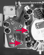
Connect your GTi panel (don't even bother with fitting it into the facia panel, you'll have to remove it again shortly) and check that everyting (expect the new meters, of course) works satisfactorily. Remove it again and let's see how we can connect the sensor wiring. When you removed your old panel, one of the connectors was a white 2-pin one, with only one wire connected. It snapped into a receptacle near the bottom of the tachometer. This is the wire coming from the 105 °C switch to the yellow warning lamp, the third from the bottom just above the connector. In the GTi panel, this bulb slot is probably empty, as it is not used. But if you twist a bulb holder into it (just use any of the bulbs on the panel for a moment) and apply 9-12 V to pin 5 of the fourth connector of the top edge and ground the lower pin of this small connector, the lamp will be lit. You won't see it from the back side, only from the front.
The temperature meter is to the left of the connector, its three connections are secured by nuts to the flexible printed circuit board. The rightmost one, closest to the connector is the feed from the sensor, connected to pin 6 of the first connector of the top edge (you can follow the wiring on the circuit board to the connector easily). Our task is to connect these two circuits somehow. I found three viable solutions (equivalent in practice):
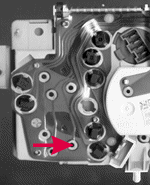
First, you can fit a connecting wire between the rightmost nut of the meter (a ring connector secured with the nut) and the right bulbholder connector (soldered to the circuit board, apply minimum heat and solder as quick as you can to avoid damage to the flexible plastic PCB; but solder it in situ, removing the PCB would be a major pain in the neck). This solution is the least destructive: you only modified the GTi panel and can refit the original one any time you want.
Second, if you don't trust your soldering skills or just don't want to experiment with the sensitive circuit board, cut the single wire going to the small connector, crimp or solder a ring or horseshoe connector to it and connect it directly to the meter under the nut. This might be the simplest solution.
Third, get an extra top edge connector from the salvage yard (any of the three), remove one of the pins, attach it to the end of the wire cut from the small connector, and fit this pin into the 10-pin white connector into position 6. With this solution you imitate the genuine GTi layout to the maximum.
Finally, refit the instrument panel into the facia and the whole enchilada to the dashboard. The speedometer cable can be reconnected by simply pushing it onto the meter stub (apply a little grease first, though, speedos tend to wobble anyway).
The next step?
You have two other meters in the instrument panel still idle: oil pressure and oil temperature. There is no wiring for them in smaller models, however, this shouldn't be a problem: just two wires going the same route the oil pressure switch wire goes, entering the engine compartment through the bulkhead under the battery (remove the battery to see and to install), crossing over the clutch cable, under the inlet manifold.
The oil pressure warning switch is located above the oil filter, on the front of the engine. A little to the right and upwards, you'll find a bolt. This bolt occupies the place of the pressure sensor. Remove the bolt (there is no oil pressure if the engine is not running, so there is no need to drain the oil, not even a drop will flow out from the hole) and fit the sensor in its place. Access is very difficult to this spot (unless you remove the alternator or the inlet manifold) but I am the living proof that it can be solved without removing those parts, reaching down with one hand through the manifold, with the other from the front, behind the radiator. Some of the hoses might block the way, remove or relocate them if necessary. If you plan to change the oil in the engine, fit the sensor at the same time. When the oil filter is removed, you can reach the pressure sensor from the bottom. Needless to say, don't try this with a hot engine...
The oil temperature sender is screwed into the sump pan on GTis. On my TRI, I found no hole for this purpose, meaning that it cannot be solved without replacing the sump pan.
If you plan to revive these meters as well, then the third connecting method (adding new pins to the white top edge connector) seems to be the best. The coolant temperature sensor came through pin 6, the oil pressure sensor should be connected through pin 2 and the oil temperature sensor through pin 7.
But I have a Series I BX!
Catalin wrote the following: "I own an '86 BX 19 GT with a Lego dashboard. After a quick check I found that it is very easy to install a supplementary sensor and a meter. [...] Just find a pair of supplementary meter and sensor from another car. VW Golf GTI, Audi 80 GTE, etc. have round meters on the center console. It is very important to have the meter coupled with its original sensor as their internal resistance differs from one another. The new sensor may require rethreading. The original thread is M14×1.25. After replacing it, make sure it doesn't leak (you may use some special sealant).
I made a plastic box (dimensions: 7×7×10 cm) and screwed it to the left side of the steering column (just under the instrument panel). The wiring is very simple, only three wires: positive feed, ground, sensor. I put a similar box on the the right side (just behind the ignition key) with an oil pressure meter. As the older engine had no hole for the pressure sensor, I needed an additional bronze housing fitted to the engine, housing both the pressure switch and the sensor."