Using a Multimeter
 A rather simple, basic multimeter is enough to check and troubleshoot the electrical parts of the car. Such multimeters can be purchased at hardware or electronics stores. The picture shows a genuine noname multimeter although I saw the very same unit under many brand names and disguises. Noname meters may not be safe if used to measure higher voltages but in the 12 V network of the car there are hardly other risks than blowing some fuses.
They can measure voltage (Volt), current (Amper) and resistance (ohm). Accuracy is not of utmost importance, however, a somewhat more expensive but robust and reliable multimeter pays for itself in the long run.
Multimeters can be either analog or digital: the analog ones have a traditional needle gauge while digital ones—like the one on the picture--a simple LCD display of generally three or four digits. Digital meters are ubiquitous today and they withstand the rugged environment in a car much better; in addition, you don't have to learn how to read the scales.
A very important parameter of every voltmeter is its internal impedance (measured in ohms per volt). Less important if you measure in the conventional parts of the electrical system but if you want to look around near the electronic circuits (like injection or ABS ECUs), a meter with an impedance of 10 MΩ or more is essential. Analog meters are usually much better in this respect: even cheap ones generally have acceptable impedance, with cheap digital meters you have to be careful (for instance, the one on the picture is rather bad as well).
How to use the meter?
You probably have an instruction manual bundled with the meter but in any way, you'll need a battery inside the meter to supply current for resistance measurement and two probes (wires, usually one red and one black) which plug into the sockets on the meter. About the battery and its location you'll have to consult the manual.
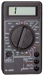
The meter has some sort of a selector switch (a rotary one like on the picture or a series of buttons) to select the required mode of operation. Voltage is represented by V or U, current by A or I, resistance by Ω (uppercase Greek omega) or R. DC (or =) and AC (or ≈) are used as modifiers to denote direct and alternate current. Simpler multimeters have numerous settings, as shown on the picture: each area (DCV, ACV, DCA or Ω) has several settings. For instance, in the 20 DCV mode you can measure between zero and 20 V direct current, in the 20 kΩ mode between zero and 20 kohm or 20,000 ohm). More sophisticated meters have only DCV or Ω modes and they select their actual measuring range automatically, informing you of the unit selected on the display.
You will find at least two sockets on the multimeter, one will be marked COM (common), GND (ground) or will show the circuit diagram of the ground, an arrow consisting of three horizontal lines as shown on the picture. The markings will inform you which is the second socket to be used for measuring V, A or Ω.
What to measure?
![]() You can measure practically everything in your car with this simple meter but at all costs avoid the high tension leads in the ignition system (the ignition coil, the distributor and the spark plugs): they operate at very high voltages which could result in a nasty or even lethal electrical shock. The meter is not capable of measuring such high voltages, anyway.
You can measure practically everything in your car with this simple meter but at all costs avoid the high tension leads in the ignition system (the ignition coil, the distributor and the spark plugs): they operate at very high voltages which could result in a nasty or even lethal electrical shock. The meter is not capable of measuring such high voltages, anyway.
By measuring resistance you can check whether a wire is broken, a sensor is working or a switch is functional. It is very important to note that while measuring resistance, you have to switch off the current in the circuit (by switching the ignition off or, if this is not enough, by disconnecting the battery). The meter wants to use its own battery to send current into the circuit to be measured and if there is some other current in the circuit, this will falsify the readout completely and can even damage the meter.
Connect the probes to the ground and Ω sockets and select the largest setting of the Ohm mode. If the probes don't touch each other, the meter will show overflow, meaning that the value measured is larger than it can display (the meter on the picture shows a left aligned digit 1, other multimeters will have different ways of displaying this condition—if in doubt, check the manual). In this case, this signals that the resistance between the two probes (as they are not connected) is practically infinitely high. If you touch the two probes together, the circuit will be shorted and the readout drops to zero (or a very small value above zero).
While measuring in practice, you'll look for these two values: overflow or infinity means a broken wire, failing switch or bad grounding contact, while (near) zero an existing and good contact. Connect the two probes to the ends of the cable or connectors of the switch (unless you want to measure an electronic circuit with semiconductors inside, it doesn't make any difference which probe connects to which end) and observe the readout.
To check the functioning of a circuit, measuring voltage is generally more rewarding than measuring resistance. In this case you have to switch the circuit on. Follow the flow of current on the circuit diagram from the battery to the ground and check at each point or connector that you still have the board voltage (12 to 14 V). To accomplish this, connect the probes to the ground and V sockets and select the largest setting of the DC Volt mode (as you can be reasonably safe that there are no hundreds of volts in the car, you can start from the 20 V range or higher). Connect the GND probe to a known good ground (an exposed metal part, bolt or connector) and touch the point to be measured with the other probe while observing the display. If you happen to swap the two probes, the meter will measure all right but will inform you about the reversed polarity by displaying a negative value. As you go along the circuit, you need to find about the same voltage along the path everywhere (a small drop is due to the resistance of the wires and components and is of no consequence but a drop of several volts shows a bad contact). If the readout drops to zero, the fault lies between this point and the last one still with adequate voltage.
The need to measure current is rare, it mostly helps reveal current leaks that flatten the battery. As the battery is capable of supplying rather high currents which could surpass the capacity of the meter, blow fuses or even burn wires and cause fire, it is best left for experienced people who will know how to measure it themselves...