Radio illumination
With the possibility of LEDs everyhere, even in all the switches, the radio cannot be left out. The buttons have LED illumination orginally, as well as the red theft deterrent warning light but the display background is provided by tungsten bulbs. But even with the LEDs, they are of a yellowish-greenish tint and rather dim, as technology two decades ago allowed. Besides, if you have part of your illumination burnt out, you'll need to repair it, anyway. So, let's see how it can be done.
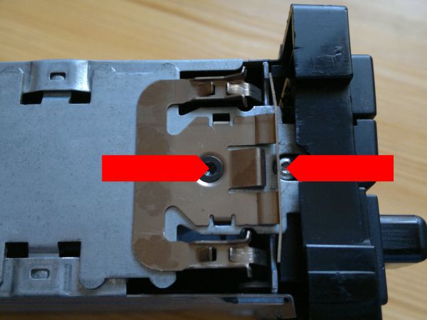
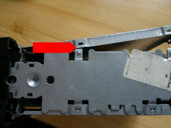
Remove the locking bracket (not absolutely necessary but very easy to do and it's easier to handle the box without it) and remove the fixing screw of the front panel as well:
Now remove the upper and lower parts of the box. Easy, just prise it at the lugs with a small screwdriver:
Now grab the handle of the flexible connector and carefully lift it from the socket:

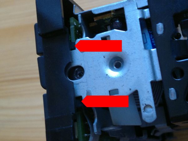
With the same small screwdriver, depress both retaining lugs on both sides and the front panel can be removed (take care of the flexible connector):
The PCB is held by six screws:

Pull the top of the socket to loosen the connector and remove the flexible connector:
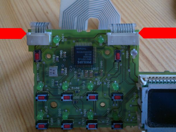
Now you have the PCB completely free. There are 16 green LEDs, one red and three tungsten bulbs buried deep under the display unit. Let's think about the LEDs first.
You could follow the procedure of the dashboard switches. Today's LEDs can provide much brighter light and you can opt for a slightly different green (or, actually, any other color, considering that the button front panel has white inserts, not colored). The LEDs have the same 560R SMD resistors like other similar LEDs in the car, although in parallel pairs and smaller than the 1206 used in other places.
The LEDs are a bit difficult to desolder, mainly because the terminals are bent. You can make it very easy if you grab a syringe needle, just the right size to fit into the PCB holes. Grind off the sharp point, leaving only a tube. If you melt the solder the your iron, you can use the needle to straighten the legs and keep it rotating until the solder solidifies again. The solder will not stick to the needle, leaving the leg perfectly separated from the hole.
If you're unable to find a fitting syringe needle, you can also cut one of the LED terminals on the component side (a small scissors will do) and then you can desolder both easily.
Replacing the LEDs is straightforward, the polarity is marked on the PCB and all the LEDs face in the same direction (including the red one). But if you decide to change the resistors, I don't recommend it unless you have experience with SMD parts. The PCB is not terribly strong, the resistors are glued in place and they are tinier than the normally already tiny 1206 parts. Follow these steps to have success:
- In order to remove a resistor, put a small screwdriver to its side, push it in perpendicular direction, heat both pads in quick succession and after a few iterations, the resistor will slide off. Don't try to lift it forcibly, the copper layer might peel off. Don't try to push it to the direction of the pad, but really at a right angle;
- Clean the pads with desoldering wick, completely. I mean it. Only leave the tinning that is impossible to remove, but don't leave any extra solder on the pad, and certainly not a visible lump;
- Flux one pad, place the new resistor in place, push it down wih forceps or a small screwdriver and using the iron with a clean tip (no extra solder!) just heat the resistor from the side until the very small amount of solder left on the pad grabs it. It won't be a strong bond, just to keep the component in place;
- Turn around the PCB, flux and solder the opposite pad with a minuscule amount of solder;
- Turn around the PCB once more, flux and solder the first pad with a minuscule amount of solder.
...