Dashboard
Changing bulbs
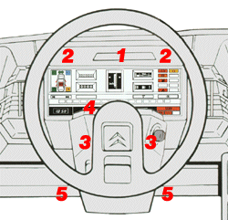
Series I (pre-1986) models: First, open the inspection panel [1] above the instruments by prising it free, then unscrew and remove the upper fixing screws [2] on both sides of the instrument panel. Undo the two screws [3] on the steering column lower shroud, remove the upper shroud [4] and then the two lower panel fixing bolts [5]. Disconnect the connectors and the speedometer cable by pulling off its sleeve. Withdraw the panel unit. Untwist the bulb holders carefully.
To remove the whole instrument panel, undo the four retaining screws.
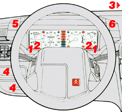
Series II (post-1986) models: First, remove the trim panel [1] between the instruments and the steering column (two screws from underneath) then the two lower retaining screws [2] now exposed—try not to let them fall or, chances are, you have to remove the lower steering column cover just to recover your screws. Then remove the upper facia tray [3] with the clock (two screws). Remove either the foglight switch panel or the cassette holder [4] from the left-hand side of the facia (assuming left-hand drive). The instrument panel facia is retained by two nuts (self-threading 11 mm nuts, later wing nuts), one can be reached through the removed foglight switch panel (or cassette holder) [5], the second through the clock tray aperture [6]. Then partially withdraw the instrument panel and disconnect the speedometer cable by pulling off its sleeve. This is already enough for the warning light bulbs to be changed. Untwist the bulb holders carefully.
To remove the whole instrument panel, disconnect the connectors from the back of the panel (there is no need to note their position as they can be refitted in the correct way only). Remove the two side screws retaining the panel, prise free the two clips from the pegs at the lower rear face. Withdraw the instrument panel from the facia--you don't need to disconnect the wiring from the four switches in the facia.
If you have the self-threading nuts, you should seriously consider upgrading to wing nuts: the first ones don't tolerate well repeated fastenings. Either you replace the whole facia panel or DIY a little bit. Here is what I did: I sawed off the plastic studs then carefully drilled a hole through the remaining stub. I fitted a long bolt into the hole, secured it with a thin nut. When in place, I secure the whole panel with a washer and a wing nut, just like the later facia panel does originally. With these nuts easy to be undone by hand and a little experience, a bulb can be changed in ten minutes.
And if you had to dismantle the dashboard because of a bulb, consider replacing all of them at once. You can buy the bulbs by the dozen in regular automotive stores (practically all European car makes use these same bulbs, so they are cheap and available everywhere; you don't need the bulb holders, just the bulbs themselves), and replacing all of them will make sure you don't have to repeat the process after only a couple of weeks...
Disassembling the panel
Once you have the whole unit out of the car (removed as described above, secured with two screws and two plastic lugs into the facia), you should separate the white housing and the plastic window in the front. There are eight lugs all around where the housing and the front panel meet. You can carefully separate them by using two or three small screwdrivers, carefully prizing one lug free and leaving the screwdriver there to keep it from engaging again, then repeating this with the other lugs.
Now you have the whole instrument panel in your hand, still as one unit, but the needles already exposed. The individual gauges are pushed into the white housing from the front (and the larger ones secured with bolts from the back). Remove the small hex bolts from the front, but be careful: the front panel of the gauges is sandwiched of two layers, a thick, transparent background panel and a thin black layer with the markings and digits, glued together. The black marked panel is somewhat larger so that it extends over the edge of the housing. You have to lift this panel off (it is only a thin layer of self-adhesive glue that keeps it there), separating it very carefully from the housing below, taking care of not to damage it because the damage will be visible. As soon as you peel the panel off and have removed all securing screws, the individual meters should come out from their place.
No backlights on the dashboard
Check with a multimeter or test lamp that you have positive feed on one of the pins of the rheostat connector, then varying voltage on the other. If so, the rheostat is OK, go on. If it's faulty, just jumper the two pins: everything should light up now. Check whether the wiper arm makes good contact. The wiring leaving the rheostat is divided into three sub-circuits: first, the instrument panel, second, the bulbs behind the heater controls and finally, the cigar lighter and the doors not closed warning panel. If only one or two sections are not lit, check the wire going there and the ground at the other end.
To check the center console lights (behind the heater control knobs) you have to remove the console.
Confusing warning lights
There are a few diodes in the instrument panel operating the STOP light so that it comes on simultaneously with any of the major warning lights. Should one of these diodes become shorted, one warning light (eg. low LHM level) can trigger another one (coolant level) erroneously. The easiest way to check this would be to short the coolant level and LHM level sensors one by one to observe whether any of them triggers a second light, too. The oil pressure switch, on the other hand, is supposed to light up everything else: this is what happens when you turn on the ignition but do not start the car yet.
The diodes are very cheap from a common electronics store, a few eurocents each, so you could renew all of them while you're at it.
Trouble with the oil level/pressure gauge
 If both functions of the combined level/pressure gauge are out of order, especially if the white scale background bulb which used to light up during the period after startup has also gone south, you should suspect the small electronic circuit attached to the backside of the instrument panel. This circuit is responsible for measuring the time elapsed after the startup, to switch between the level and pressure measuring modes and to operate the mentioned bulb. First, check for loose contacts or bad soldering joints but if this fails to reveal the problem, you have to troubleshoot this circuit the usual way. If you have no experience with electronics, your only option is to find a replacement unit at a salvage yard or to swap one over from a friend's car or at a garage.
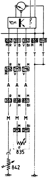
If one of the functions is OK, you can proceed with checking the rest of the circuit. The pressure sensor [842] is a simple potentiometer. Locate it on the front of the engine, remove the connector and attach an ohmmeter between its terminal and the ground. You should see the resistance change as you rev the engine, just like the needle on the instrument panel used to move. If it works by itself, check the wiring from the engine bay to the instrument panel (there is a connector right where the wiring disappears under the battery, then another one inside the cabin, then finally the edge connector of the instrument panel) for an open circuit. If the wiring was good, repeat the ohmmeter measurement where the wire reaches the instrument panel just to be sure. If your meter shows a changing resistance but the instrument panel gauge does not work, it must be the gauge or the switching circuit after all.
The level sensor [835] is, unfortunately, somewhat more complicated. The picture on the diagram is misleading, it is not a potentiometer; it operates on the principle that the resistance of conductive materials changes with the temperature. The circuit sends a constant current into the sensor and looks for resistance change. The time required for the resistance to reach a certain limit depends on the time required for the sensor wire to reach a certain temperature. However, this second one is influenced by how deep the sensor wire is submerged into oil as the oil cools the sensor wire and lengthens the warming up period. You can check whether the sensor wire is broken (the resistance should be somewhere below 20 ohms) but you cannot check its correct functioning by simple measurements. In this case the only option is to swap it with another one from a donor car. The sensor is located in an awkward place, screwed into the crankcase from behind. Unless you have easy access to an inspection pit and don't care, check the wiring first to rule out all other failures before you go for the sensor.
The diagram in the Haynes manual (under the title All models from 1987) is incorrect: it shows separate gauges, not the combined level/pressure one. Use the diagram presented here instead.
Digital clock brightness
Many people complain about the back illumination of the digital clock: it is quite comfortable during the night that the clock dims when the headlights are switched on, however, driving with headlights on in daylight (in some countries this is even compulsory) leaves to clock too dim to be read. Modifying it, however, it very simple. The clock has three 12 V inputs, one of them going through a common resistor inside the clock, dimming the light. All you have to do is to change this resistor (or substitute it with a simple wire, if you prefer no difference between the daylight and night illumination). Measure the resistance of this resistor (with one of its terminals desoldered) with a simple multimeter and then halve this value to start with. If you are not yet satisfied, modify the resistance accordingly. Be sure to have a substitute resistor with the same power rating (that is, of the same size).
Removing the clock is easy, start with the facia tray (secured by two screws), slide the clock from its holder, undo two screws and twist the light bulb free. Take care of the LCD panel and the special connectors between the panel and the circuit board.
Alternatively, you can connect the clock to the instrument illumination rheostat. You'll have to cut both wires going into the clock (connectors #1 and #2) and connect the first one to the rheostat. Note that there is a third input, too, but this should remain at 12V constantly, otherwise the clock will forget the time when you park the car. Then, independently from the headlamps, you can always adjust the brightness of the clock together with the other instruments.
A more radical modification
But no matter how you modify the original setup, it might be better but not perfect. The actual problem is that we have three different situations: daylight with and without headlights, plus night with headlights (actually, we could also count night without headlights but this is not that important) but only two settings of the clock. If we make it brighter with the headlights on so that we can see it in the daylight, they will be too bright during the night, and vice versa. Connecting the clock to the dashboard illumination rheostat does away with this problem but only at the price of constantly adjusting the rheostat to the changing environment.
This situation is dictated by the design of the clock, namely, it is of the transparent type, requiring back illumination to be seen at all, in contrast to reflective displays used in watches and calculators, relying on the ambient light in front of the panel to make the digits visible. If such a display could be used, the back illumination would only be used during the night, making no difference whatsoever to the readability in daylight.
And such a display can be used but this entails the complete renewal of the clock unit. Many companies manufacture small, standalone LCD clock units that could be used instead of the original one. I chose a special one: Conrad Electronics in many countries sells a wide selection of clocks and watches that are controlled by radio signals coming from a special radio station near Frankfurt, Germany. The station driven by an atomic clock sends precise time information (precise to one second in one million years) which can be received approximately up to 1,000 km distance. There is no need (or possibility) to set this clock, it synchronizes itself as soon as it comes to life, checks the exact time every hour on the hour, and if the reception is poor, it keeps going like a regular digital clock. Switching to Daylight Savings Time and back is automatic as well.
The unit is rather small, it fits into the original housing nicely, although the front opening has to be enlarged accordingly. The original clock can be discarded but retain the small circuit board with the connector. Cut out the middle of the PCB so that it goes around the protruding back of the new clock unit. Solder two small bulbs on the two sides where the clock unit housing has its openings to let the light in and connect them to the remnants of the circuit board so that they light up when the headlights are switched on. If you prefer green for the illumination, you can either paint the bulbs or disassemble the clock unit and place a transparent green plastic sheet behind the display (unfortunately, the one from the original clock cannot be used, it is too small: the new clock is wider because it displays the seconds as well).
This is already enough but the back illumination will not be perfect: too bright at the sides and practically absent in the middle. I helped with another Conrad product: their backlighting kit for LCD multimeter panels. This kit consists of a specially formed plastic back panel which conducts and distributes the light quite evenly, even if it is lighted only from the sides (originally, small green SMD LEDs light it up from the sides and it does give a nice, homogenous back illumination. You can peel off this panel from its original circuit board in the kit, cut it to shape so that it will fit into the clock unit, just behind the display and the green sheet. It can be cut with knife or scissors but be careful, it breaks easily. Leave two wings on the sides which will protrude from the clock unit housing: those wings will actually receive the light of the bulbs and lead it into the unit.
Failing 'doors properly closed' symbols
The switches are in the locks themselves (not to be mixed with the door courtesy switches!), the hood open warning switch is right in front of the hood lock. There are two possible causes for the failure.
First, the lubricants from the lock can get into the switch and make the connection unreliable. The best (sometimes the only) way to correct this is by removing the lock and spraying a contact cleaner into the switch, however, this implies removing the interior trim and lots of rods and nylon fasteners (especially with central locking), probably all greased. The switch itself is at the rear end of the lock and you could be able to reach it through the round hole in the door edge near the lock grommet, however, you should remove at least one of the locks to see the exact location of the switch for yourself.
The second problem is not so easy to repair. One of the connectors in the switch is also the spring. After several years of usage, this connector brakes and the only remedy is to replace it, unfortunately, together with the lock. Be careful with the salvage yards as older locks might suffer from the same problem: even if they work when you buy them, who knows their life expectancy? It is possible to disassemble the lock and the switch, and to try to cut a similar connector from a thin copper plate, but this would be a real DIY challenge.
If the whole panel is out of order, check the 12V feed on pins #6 (warning lamps) and #8 (background lighting) of the green connector on the back of the panel when the ignition is on. The feed comes through pin 2 of the main board connector IV/4 (6-pin yellow). The panel itself can be easily removed: open and withdraw the coin tray, release the warning panel retaining clips on the left side and withdraw the panel.
Killing the self-cancelling indicator (Series II)
Remove the steering column lower shroud (two screws at the bottom, two in the middle, one under the steering wheel and two from the front, behind the steering wheel, accessible after rotating the wheel). Disconnect the wiring to the instrument lighting rheostat.
There is a plastic stud protruding approximately 3 mm from the left column switch, on the side facing the steering wheel. When you turn the switch to either left or right, the stud jumps out to some 1 cm what makes it to stand in the way of a rim rotated together with the steering wheel. The internal mechanism of the switch allows the rim edge to pass over the stud in one direction but to get entangled in it on the way back. It might seem complicated in writing, but just try to experiment with it: turn the indicator to the left, then you can pull the stud down freely but if you push it up, the switch is cancelled. Turn it to the right and the stud works in the opposite way. Two small springs are responsible for pushing the stud out when needed.
Consequently, all you have to do is to render this stud unusable, what can be accomplished in several ways: the simplest but most destructive way is to cut its protruding end off with cutting pliers or another convenient tool. There is no need to remove the whole protruding part, just cut at the same 3-4 mm position where it ends with the turn indicator switch in neutral position. A more complicated but cleaner way would be to remove the stud and the two springs. However, I would not recommend taking the switch apart, it's a pain in the neck to reassemble it again. But if you do, remove one of the two half-housings carefully. Note how the various parts connect together. There are several springs inside and if you start turning or switching the stalk with the case open, everything will pop out and it will be difficult (although certainly not impossible) to put everything back in order without the preliminary notes. While you are at it, don't forget to clean the contacts and to grease the moving and rotating parts.
In need of a self-cancelling indicator (Series I)
Unfortunately, the most you can do is to install a warning beep to remind you not to forget to cancel the indicator. Buy a piezo buzzer in an electronics parts store (choose one which has an integrated oscillator, ie. a simple 12 V feed is enough to make it buzz) and two 1N4001 ??? diodes. Tap into the green wires coming from the main board connector I/3 (a 10-pin white connector) pins #7 and #8. Connect the anode (the end without the circular marking on the body) of each diode to these wires, join the cathodes of the diodes and connect them to the positive terminal of the buzzer. Ground its negative terminal.
If the buzzer is too loud, find a suitable plastic box, stuff it with a spongy sound insulating material until you reach a sound level that can be heard even when your radio is on but is not too aggressive and annoying.
You might omit the diodes and tap the buzzer positive directly into the wire coming from connector IV/1 (10-pin yellow connector) at pin #4, however then the buzzer will sound not only with the indicator lights but with the hazard lights as well.